The principles of organizing local networks. Local area networks of an enterprise Local area network of a small enterprise
- Performance. It is provided by a well-designed architecture without bottlenecks and the use of Hi-end equipment with high bandwidth, in particular, modular switches at the core and aggregation level.
- Reliability and resiliency. Provided by the construction of fault-tolerant logical topologies and protocols for automatic rebuilding of network traffic paths in the event of failure of individual devices, without interruption in the operation of the LAN. At the level of technical means - duplication of equipment of key nodes and its components (power supplies, control modules, etc.), as well as communication channels.
- Management and monitoring. Provided by the implementation of an integrated management and monitoring system for all network equipment. Typically, for maximum compatibility, a control and monitoring system from the same manufacturer as the network equipment used is used. But third-party solutions can also be used, which sometimes have not the worst functionality.
- Protection and control. It is ensured by the end-to-end application of security policies along the entire path of network traffic. Policy management, security log analysis, and event correlation are centralized.
- Scaling. It is achieved by conditionally dividing the entire network infrastructure into separate functional modules and using the classic three-tier architecture with clearly defined levels of access, aggregation and network core. This allows you to flexibly expand the capabilities of each module and add new modules. At the level of technical means - the use of modular switches with high bandwidth and port capacity. The modular architecture allows you to optimize initial costs and expand port capacity as needed.
- Standardization and unification. It is ensured by the use of only approved standard solutions and service regulations. Whenever possible, open standard protocols and technologies are used to reduce dependence on proprietary solutions and individual vendors. Unification also promotes maximum interoperability of all components of the network infrastructure and reduces the cost of its maintenance.
- The costs should be justified, but should not constrain the scope of the proposed solution.
Kirov Regional State Educational
budgetary institution of secondary vocational education
"Kirov Aviation College"
Local area network of an enterprise
Student of group B-32
K.V. Osotova
Teacher
Kirillova L.A.
Introduction
For the first time, the idea of connecting several independently operating computers into a single distributed computing system came to engineers back in the mid-60s of the XX century. And the first successful experiment on the transfer of discrete data packets between two computers was carried out in 1965 by a young researcher from the Lincoln laboratory of the Massachusetts Institute of Technology Larry Roberts. The data transmission algorithms proposed by Roberts largely served as the basis for the ARPANet global computing network, built in 1969 at the initiative of the American Advanced Research Projects Agency (ARPA), and it subsequently, merging with several other existing at that time networks, has become the foundation on which the modern Internet has grown.
The super-rapid development of computer technology has led to an enormous growth in the computer park.
A local area network (LAN) is a collection of computers and other computing equipment (active network equipment, printers, scanners, etc.), connected by cables and network adapters and running a network operating system.
If computers are not geographically separated (located within one or two buildings), then it is not difficult to organize a local computer network, which will be economically viable.
There are many advantages of creating a local network: such a network can be used for word processing, act as its own information system, an external database, to perform numerical calculations, be an information system in management, planning, accounting, design, etc.
The main components of a LAN are:
workstations;
interface boards;
network servers;
Each of the LAN devices is connected to a data cable that allows them to communicate.
The aim of the course project is to create a college computer network, which consists of eight buildings, each of which consists of two floors, which should be able to provide network users with a shared use of the resources of all computers. There are 2 workgroups on the floor, each of which includes 10 workstations.
The developed local area network must meet the requirements of reliability, speed and expandability.
1 Analysis of the design assignment
1.1 Initial data
1.1.1 Survey of the selected room
The aim of the project is to design computer network for college. It includes 8 buildings with 2 floors. The distance between buildings is shown in Figure 1 (in meters).
Figure 1 - Layout of college buildings
1.1.2 Location of computers in workgroups
Table 1 - Distribution of workstations
|
Used floors |
Number of workstations |
Distance between working groups |
||
1.2 Choice of technology
Network technologies can significantly increase the efficiency of the use of computers, allowing you to create information systems that provide solutions to problems of remote and automated learning, information storage, document flow, messaging and the organization of group work on projects.
It is important to make a reasonable choice of the structure of the college's local area network, which allows not only to quickly build a simple and fairly effective information system, but also to choose a solution that will reduce the cost of effort and resources, allowing you to distribute the load between the computing networks of college departments.
Ethernet is one of the most common technologies used in computer networks. Today, most network adapters are equipped with interfaces that support speeds of 100 Mbps, 1 Gbps, 10 Gbps.
Advantages of using technologies in control systems:
- reduction in the cost of jobs - no need to develop or pay for specialized software in the workplace;
- reduction in the cost of support - achieved due to the lack of specialized software at workplaces;
- reducing the cost of remote monitoring - the use of publicly available communication channels allows monitoring when minimum costs to organize connection to the system;
- Simplification of staff training - achieved by using a uniform user interface at all workplaces;
- simplification of integration with external ISs - the use of open standards allows you to integrate with systems built using similar technology;
Disadvantages:
- the lack of a guaranteed time for delivery of information - there is a whole class of objects for which control in hard real time mode is required, in this case additional costs are required to reserve the necessary channel bandwidth, which is not always cost effective;
- the lack of standardized means of protecting information - additional costs are assumed for the development of a proprietary system for differentiating access to resources and protecting information in public networks;
- development of telecommunication and network technologies.
FastEthernet (IEEE 802.3u) technology is an evolutionary development of the classic Ethernet technology. Its main advantages are:
- increasing the throughput of network segments up to 100 Mb / s;
- saving the Ethernet random access method;
- preservation of the star-shaped network topology and support for traditional data transmission media - twisted pair and fiber-optic cable.
These properties allow for a gradual transition from 10Base-T networks - the most popular Ethernet option today - to high-speed networks that maintain a significant continuity with a well-known technology: FastEthernet does not require a radical retraining of personnel and replacement of equipment at all network nodes. The official 100Base-T (802.3u) standard has established three different specifications for the physical layer (in terms of the seven-layer OSI model) to support the following types of cabling systems:
- 100Base-TX for two-pair cable on unshielded twisted pair UTP Category 5, or shielded twisted pair STP Type 1;
- 100Base-T4 for a four-pair cable on an unshielded twisted pair UTP Category 3, 4 or 5;
- 100Base-FX for multimode fiber optic cable.
1.3 Topology selection
The term topology, or network topology, refers to the physical location of computers, cables, and other components of a network. The topology of the network determines its characteristics. In particular, the choice of a particular topology affects:
- on the composition of the required network equipment;
- on the characteristics of network equipment;
- on the possibility of expanding the network;
- on the method of network management.
Each network topology imposes a number of conditions. For example, it can dictate not only the type of cable, but also the way it is laid. Topology can also determine the way computers interact on a network. Various types topologies correspond different methods interactions, and these techniques have a large impact on the network.
There are 3 basic topologies:
- bus - is a common cable (called a bus or trunk) to which all workstations are connected. There are terminators at the ends of the cable to prevent signal reflection.
- a ring is a topology in which each computer is connected by communication lines with only two others: from one it only receives information, and to the other it only transmits. On each communication line, only one transmitter and one receiver works. This eliminates the need for external terminators.
- star - the basic topology of a computer network, in which all computers on the network are connected to a central node (usually a switch), forming a physical segment of the network. Such a network segment can function both separately and as part of a complex network topology (usually a “tree”). All information exchange is carried out exclusively through central computer, on which a very large load is imposed in this way, so it cannot do anything other than the network. As a rule, it is the central computer that is the most powerful, and it is on it that all the functions of managing the exchange are entrusted. In principle, no conflicts in a network with a star topology are possible, because the management is completely centralized.
Star topology - In star networks, network media connects a central hub to every device on the network. This topology uses central point control, and communication between devices connected to the network occurs via point-to-point links between each device and a center channel or hub. All network traffic in a star topology goes through a hub. First, the data is sent to the hub, and then the hub forwards it to the device according to the address contained in the data. In star networks, a hub can be active or passive:
- passive - connects the sections of the network data transmission medium;
- the active concentrator not only connects the sections of the transmission medium, but also regenerates the signal, i.e. works like a multiport repeater. By performing signal regeneration, an active hub allows data to travel over greater distances.
Star topology benefits:
- ease of maintenance: the only area of concentration is the center of the network;
- allows you to easily diagnose problems and change the gasket scheme;
- simple in terms of design and installation;
- reliability - if one of the sections of the network data transmission medium is cut off or short-circuited, then only the device connected to this point loses its connection. The rest of the network will function normally;
- easy to add workstations.
In a sense, the advantages of star topology can also be considered its disadvantages. For example, having a separate piece of cable for each device makes it easy to diagnose failures, however, this also leads to an increase in the number of pieces. This increases the cost of installing a star network. Another example: a hub can simplify maintenance because all data flows through this central point; however, if a hub fails, the entire network stops working. This topology is suitable for this task.
1.4 Choice of cabling
The basis for choosing a cable system is the development of specifications for communication equipment in a computer network of working rooms, indicating the location of PCs and cable lines in them.
The choice of a cable system depends on the intensity of network traffic, requirements for information protection, maximum distance, requirements for cable characteristics, and the cost of implementation.
Twisted pair (twistedpair) - a type of communication cable, is one or more pairs of insulated conductors, twisted together and covered with a plastic sheath. Typically Ethernet 10Base-T uses a twisted pair cable. One transmit and one receive (AWG 24).
Thin coaxial (RG-58 or "Thin Ethernet") is an electrical cable consisting of a center conductor and a shield and used to transmit high-frequency signals. Characteristic impedance 50 Ohm, diameter 0.25 inches, maximum length of the cable segment 185 meters. Rule 5.4.3 - 10BASE2 Standard applies. Coaxial cable is more noise-resistant, signal attenuation in it is less than in twisted pair.
Optical fiber is an optical waveguide - a round rod made of an optically transparent dielectric. Because of their small cross-sectional dimensions, optical waveguides are commonly referred to as fiber-optic LEDs or optical fibers.
After analyzing the characteristics different types cable, physical location of computers, choose a 10Base-T twisted pair cable and fiber optic. Twisted pair and fiber optic complement each other, so they can be used together. In this case, the fiber-optic cable is for building the backbone, and the twisted pair is for creating a network inside the premises.
Equally important in the design of a computer network is the choice of a cable subsystem, since a reliable aircraft provides reliable connections. All connections in the network must be of high quality, unreliable contacts and other physical damage are unacceptable. Important attention is paid to this, because finding an open or damaged connection in a faulty network is a very time-consuming task.
The cable system is the most important physical medium that connects computers into a single whole, without which the functioning of the local network as such is impossible.
The importance of the cable system is determined not only by its fundamental nature in the construction of computer networks, but also by the fact that the wrong choice of a network cable can lead to a significant decrease in network performance or its incorrect operation. That is why it is extremely important to choose the right network cable, to build a cable system competently and professionally. Recently, structured cabling has been increasingly used as such a reliable basis.
A structured cabling system (SCS) is a set of switching elements (cables, connectors, connectors, cross-over panels and cabinets), as well as a technique for their joint use, which allows you to create regular, easily expandable communication structures in computer networks.
SCS differs in that, if necessary, the configuration of connections in the network can be easily changed, that is, add a switch, computer, segment, etc. The structured cabling system is built in such a way that each workplace must have sockets for connecting workstations to them. This can save money in the future, as changes in the connection of new devices can be made by re-connecting existing cables. Such a system is built hierarchically, with the main highway and numerous branches from it.
The main principle of SCS is that it should cover the entire building.
Using SCS instead of chaotically laid cables gives many advantages:
- versatility - SCS can become a single medium for transferring computer data in a local computer network, organizing a local telephone network, transferring video information, if its organization is clearly thought out;
- increased service life - the aging period can be 10 - 15 years, which is even very good;
- the ability to easily expand the network;
- it is possible to change the cable type in a separate subnet independently of the rest of the network;
- reliability - SCS has increased reliability, since the manufacturer of such a system guarantees not only the quality of its individual components, but also their compatibility.
SCS includes a horizontal subsystem (within a floor), a vertical subsystem (between floors), a campus subsystem (within one territory with several buildings).
1.5 Horizontal subsystem
The horizontal subsystem is characterized by a large number of cable branches, as it must be routed to each user outlet. Therefore, for the cable used in horizontal wiring, increased requirements are imposed on the convenience of making branches, as well as the convenience of laying it indoors. When choosing a cable, the following characteristics are taken into account: bandwidth, distance, physical security, electromagnetic interference immunity, cost.
The preferred medium for horizontal cabling is twisted pair, both shielded (STP) and unshielded (UTP).
Category 5 UTP is an unshielded copper cable made up of four cable pairs, each with a color and pitch. Usually two pairs are for data transmission and two for voice transmission.
STP is a twisted pair of wires that are wrapped in an insulating shield. This cable allows data to be transmitted over a longer distance and supports more nodes than UTP. The presence of the screen makes it more expensive, but it has good noise immunity and protects the data from electromagnetic radiation.
The cable for the horizontal subsystem of this network is UTP cat.5 twisted pair.
1.6 Vertical subsystem
The vertical cable that connects the floors of the building must transmit data over long distances and at a faster speed than the horizontal cable. It consists of longer cable lengths, the number of branches is much less than in the horizontal subsystem.
This network uses a fiber optic cable for these purposes.
1.7 Campus subsystem
The campus subsystem of this network is an interconnection of several buildings with the help of a cable duct, laying an external fiber-optic cable.
2 Description structural diagram
In accordance with the initial data selected by the topology and technology of the network, the cable system, a structural diagram of the local area network has been developed, which is shown in drawing 230106.KPSD05.018E1.
The network consists of eight buildings. The connection between them is carried out using the GigabitEthernet technology, since this technology provides traffic up to 1000 Mbit / s. Fiber optic cable is used to connect buildings.
To provide the necessary traffic up to 100 Mbit / s, Fast Ethernet technology is used in all buildings. Workstations in a workgroup are connected through switches. All switches of groups of one floor are connected to a floor switch. Further, the connection between them is carried out through the building switch. This switch must have at least one optical port to connect to the main switch in the server room. A twisted pair cable is used to connect the switches.
The network in Building 1 includes a server room that houses the InternetServer, DataServer, and the main switch. All other buildings, except for floor switches, are connected to it. In addition to the usual ports, the main switch must have four optical ports in order to be able to connect all buildings through an optical cable.
The first working group includes 15 workstations on the first floor, the second group - 15, the third - 10 computers on the second. There are four (1,2,3,4) Gigabit Ethernet switches in the building. The main Gigabit Ethernet switch with fiber optic is located on the first floor, which connects all workgroups in the building and establishes a fiber optic connection through the duct to the second, third and fourth buildings. The working groups of the building are united by switch 1. Also on the first floor of building 1 there is a main server serving for network administration and program control network operation, establishes a connection with the provider using an ADSL modem.
On the first floor of building 5, the switch establishes a similar connection to buildings 6,7,8. The network in buildings 1 and 5 is interconnected using switches and fiber optic. Also on the ground floor there is the main server, which serves for network administration and software control of the network operation, establishes a connection with the provider using an ADSL modem.
The network in buildings 2,3,4,6,7,8 includes 2 workgroups on the first and second floors, each of which includes 10 workstations, so they are connected by one switch. In total, buildings have five Gigabit Ethernet switches, the main Gigabit Ethernet switches with fiber optic are located on the first floors of buildings, which connect all departments of each building, and are connected via fiber optic between neighboring ones.
3. Justification of the wiring diagram
Based on the structural diagram, the selected technology and network topology, cable system, a wiring diagram of the network was developed, shown in drawing 230106.
Switches located in workgroups must have 24 ports for twisted pair connection, of which 15 are the maximum number of workstations in the group, and the rest are for possible expansion of the local network. Workstations are connected to the workgroup switch through patch panels.
The switch connects to the patch panel through a 0.5 meter patch cord, then a 1.5 meter patch cord leads from the patch panel to an RJ-45 category 5e socket located directly in the workstation. Wall-mounted cabinets are used as wiring closets in workgroups and on floors.
Since there are 2 working groups on floors 1,2 of each building, the switches are interconnected using an unshielded twisted pair (UTP 5e), which is included in a special patch panel, from which the patch cord is connected to the common floor switch. The floor switches are connected in the building switch via a twisted pair cable (UTP 5e) passing into the patch panel, from which the patch cord enters the building switch.
Each switch has a fiber optic input. The building switch is connected to a common LAN switch in the server room via a fiber optic cable (FO-ZIP-IN-50-2-FRPVC). The presence of fiber optic inputs on all switches allows this LAN to be expandable in the future.
The server room with Internet Server and Data Server is located in the first and fifth buildings on the first floor. The main switch has 4 additional optical ports to connect common switches in the rest of the buildings. The web server performs the function of connecting to the Internet using a fiber optic cable.
For fiber-optic connection between the provider's equipment and the server, it has an additional network card.
4. Choice of network equipment
4.1 Description of network equipment
There are many factors to consider when choosing network equipment, including:
- the level of equipment standardization and its compatibility with the most common by software;
- the speed of information transfer and the possibility of it further increase;
- possible network topologies and their combinations (bus, passive star, passive tree);
- method of control of exchange in the network (CSMA / CD, full duplex or marker method);
- permitted types of network cable, its maximum length, immunity from interference;
- the cost and technical characteristics of specific hardware (network adapters, transceivers, repeaters, hubs, switches).
Network equipment - devices that make up a computer network. Conventionally, there are two types of network equipment:
- active network equipment - equipment that is capable of processing or transforming information transmitted over the network. Such equipment includes network cards, routers, print servers;
- passive network equipment - equipment used for the simple transmission of a signal to physical level... These are network cables, connectors and power outlets, repeaters and signal amplifiers.
To install a wired computer network, we first need:
- network cable and connectors (called connectors);
- network cards - one in each PC on the network, and two on a computer that serves as a server for accessing the Internet;
- a device or devices that transfer packets between computers on the network. For networks of three or more computers, you need a special device - a switch that unites all computers on the network;
- additional network devices. The simplest network is built without such equipment, however, when organizing a general Internet connection, using shared network printers, additional devices can facilitate the solution of such tasks.
Currently, there is a diverse number of firms specializing in the production of network equipment. The network equipment market is represented by firms that have already won worldwide recognition in the quality and reliability of their products, and firms that have not yet fully established themselves on the world market, but have great prospects in their development. At the moment, the following dominate among the firms producing network equipment: Cisco, 3Com, HP, D-Link.
The equipment of the companies presented is rarely used in the construction of networks, and it is more rational to choose equipment from another company to ensure compatibility, since there are various forms and methods of control. With this in mind, we choose D-Link as a leading provider of innovative, practical and highly efficient voice and data network products, services and solutions for companies of all sizes and public sector organizations.
cable server computer montage
4.2 Network conductors
This group includes various network cables (twisted pair, coaxial cable, fiber optic). There are several categories of twisted-pair cables that are labeled CAT1 to CAT7. In local networks of the Ethernet standard, twisted pair CAT5 is used. For work with twisted pair cables, RJ-45 connectors are used.
4.3 Network switches
Currently, switches (or, as they are called, switches) are used in local networks. These are devices that have their own processor, internal bus, and buffer memory. If a hub simply forwards packets from one port to all others, then the switch analyzes the addresses of the network cards connected to its ports and forwards the packet only to the correct port. As a result, useless traffic on the network is dramatically reduced. This can greatly increase network performance and provide faster data transfer rates in networks with a large number of users.
The switch can operate at 10, 100, or 1000 Mbps. This, as well as the network cards installed on computers, determines the speed of the network segment. Another characteristic of a switch is the number of ports. This determines the number of network devices that can be connected to the switch. In addition to computers, they are print servers, modems, network disk drives and other devices with a LAN interface.
When designing a network and choosing a switch, you need to take into account the possibility of expanding the network in the future - it is better to purchase a switch with a few more ports than the number of computers in your network at the moment. In addition, one port should be kept free in case of interconnection with another switch. At present, switches are connected by a conventional twisted pair of the fifth category, exactly the same that is used to connect each computer on the network to the switch.
4.4 Additional network equipment
In a local network, you can use various additional equipment, for example, to connect two networks or to protect the network from external attacks:
- a print server, or print server, is a device that allows you to connect a printer that does not have its own network port to the network;
- the repeater is designed to increase the distance of the network connection by amplifying the electrical signal;
If you will use a twisted pair cable longer than 100 meters in a local network, repeaters should be installed in the cable break every 100 meters. Using repeaters, several detached buildings can be connected with a network cable.
- router (or router) - network device, which, based on information about the network structure, according to a certain algorithm, selects a route for forwarding packets between different network segments.
Routers are used to combine networks of different types, often incompatible in architecture and protocols (for example, to connect Ethernet to a WAN). Also, the router is used to provide access from the local network to global network The Internet, while carrying out the functions of a firewall.
A router can be presented not only in hardware, but also in software. Any computer on the network with the appropriate software, can serve as a router.
Switches:
- D-Link DES-1026G, 24-port fast ethernet switch 10 / 100Mbps, 2-port 10/100 / 1000Mbps;
- D-LinkWebSmartPro switch with 24 10/100 / 1000Base-T ports with PoE (802.3af) support + 4 100 / 1000BASE-T SFP ports and power saving function.
Equipment for Internet connection - DSL-564T ADSL Eth modem Router 4 LAN & 1 ADSL port, IP, Annex B.
- AquariusSrvN70 D11 (211300 / 4D / 1024 / HDD 73 GbU320 SCSISCA 10 krmp).
Cable system:
- Hyperline HF1IA01G5 (FO-ZIP-IN-50-2-FRPVC) Fiber optic cable 50/125 (OM2) multimode internal, zip-cord, 2 cores;
Category 5 unshielded twisted pair UTP;
RJ-45 UTP 5e socket;
3C996-SX GigabitEtherLink, OEM / 1000Base-SX, PCI - For PCs with data transfer rates over 100 Mbps;
3com 10 / 100Mbps-inpack FastEthernetAdapter Rj-45 - For PCs with data transfer rates less than 100 Mbps;
5. Calculating the cost of equipment
5.1 Calculation of the cost of purchased equipment is shown in table 2.
Table 2 - Calculation of the cost of equipment
|
Name |
Price, rub.) |
Quantity |
|||
|
D-Link DES-1026G, 24-port fast ethernet switch 10 / 100Mbps, 2-port 10/100 / 1000Mbps |
|||||
|
D-LinkWebSmartPro switch with 24 10/100 / 1000Base-T ports with PoE (802.3af) support + 4 100 / 1000BASE-T SFP ports and power saving function |
|||||
|
DGS 10 / 100Mbps-inpack Fast Ethernet Adapter Rj-45 |
|||||
|
UTP Category 5 Unshielded Twisted Pair |
|||||
|
Hyperline HF1IA01G5 (FO-ZIP-IN-50-2-FRPVC) Fiber optic cable 50/125 (OM2) multimode internal, zip-cord, 2 cores |
|||||
|
D-Link DSL 2540U / BB / T1A Modem |
|||||
|
Neomax NM13001-005GN Patch cord UTP 0.5m Cat 5E green |
|||||
|
NM13001-015GN Patch cord UTP 1,5m Cat 5E green |
|||||
|
Network equipment cabinet |
|||||
|
Server Absolute DS 2x5506x5U Dual Xeon E5506 / 8Gb / 3x600 10K SATA HS-RAID / TS700-E6-RS8 / DVDRW / Pedestal |
|||||
|
Hyperline SB-GTS2-8P8C-C5E-WH RJ-45 socket, double, category 5e, wall-mounted |
|||||
Since the physical location of the working groups in buildings is not known, the approximate length of the fiber-optic cable for external installation was calculated based on the fact that the distance between the floors of the building is 10 meters, the cable length for the distance between building 1 and building 2 is about 150 meters.
To calculate the approximate length of the twisted pair for indoor installation, the cable length between the working groups was taken as 50 meters. The length of the twisted pair is calculated at the rate of 100 meters for each workgroup.
The approximate cost of the projected local area network is 792,255.4 rubles.
6. Analysis of the information system
6.1 Server hardware
The choice of a network operating system is influenced by the amount of money that can be spent on network hardware and software. One of the most powerful and fastest servers for performing any task is the AbsoluteDS 2x5506x5UDualXeonE5506 / 8Gb / 3x600 10KSATAHS-RAID / TS700-E6-RS8 / DVDRW / Pedestal server. Two Xeon processors provide the required power in any application, and three SATA HDD 600Gb 10000rpm always provide the required speed, capacity and reliability.
Table 3 - Server configuration
|
Configuration: |
||
|
Platform |
ASUS TS700-E6-RS8 (LGA1366, i5520, PCI-E, SVGA, SATA RAID, 4xHS SAS / SATA, 2xGbLAN, 12DDRIII, 620W HS) |
|
|
CPU |
||
|
CPU |
CPU IntelXeon E5506 2.13 GHz / 1 + 4Mb / 4.80 GT / s LGA1366 |
|
|
Cooler for processor |
Pasive Cooler Intel for 2U System |
|
|
RAM module |
||
|
RAM module |
Kingston KVR1066D3D8R7S / 2G DDR-III DIMM 2Gb PC3-8500 ECC Registered with Parity CL7 |
|
|
RAM module |
Kingston KVR1066D3D8R7S / 2G DDR-III DIMM 2Gb PC3-8500 ECC Registered with Parity CL7 |
|
|
RAM module |
Kingston KVR1066D3D8R7S / 2G DDR-III DIMM 2Gb PC3-8500 ECC Registered with Parity CL7 |
|
|
HDD |
||
|
HDD |
HDD 600 Gb SATA 6Gb / s Western digital VelociRaptor WD6000HLHX 10000rpm 32Mb |
|
|
HDD |
HDD 600 Gb SATA 6Gb / s Western Digital VelociRaptor WD6000HLHX 10000rpm 32Mb |
|
|
DVD ± RW drive |
DVD ± R / RW & CDRW Optiarc AD-7241S Black SATA (OEM) |
|
|
Raid Controller |
yes, it is possible to build RAID arrays 0, 1, 10, 5 x Raid from SAS and SATA devices |
|
|
Video card |
Aspeed AST2050 Video |
|
|
2 network controllers Intel 82575EB 10/100/1000 Mbps |
||
|
8 hot-swappable SAS and SATA HDD cages. |
||
|
Additionally |
it is possible to correct this configuration by the client |
6.2 Hardware of workstations
Requirements for computers used as workstations are determined primarily based on the tasks that will be solved on these workstations.
If the workstation is connected to a network, it does not need a hard drive or floppy disks.
The benefits of a diskless workstation are clear. In addition to reducing the cost of the station itself, the risk of virus infection is excluded - there is no floppy disk, and there is no way to bring a virus.
In addition, it provides "hardware" protection of information from unauthorized copying. Users will not be able to copy information from the file server, since there is physically nowhere to write it.
For normal operation, workstations are required with the following minimum set of technical characteristics:
RAM 4 GB;
Quad-core processor, frequency from 2.4 GHz;
Disk drive 500 GB;
Operating room Windows system 7.
6.3 Software selection
In local networks with a dedicated server, special operating systems are used on the server to ensure reliable and efficient processing of many requests from user workstations.
Workstations of such a local network can use any operating system, for example Windows, etc., and a driver must be running to provide access to the local network.
In networks with a large number of servers, the Windows Server 2008 operating system is often used because it provides a convenient means for centralized resource management of such networks. Since it is the management of network resources that usually accounts for more than half of the operating costs.
Hardware Requirements Windows Server 2008 are shown in Table 4.
Table 4 - Server hardware requirements
|
CPU |
1 GHz (x86) or 1.4 GHz (x64) |
2 GHz and above |
|
|
512 MB RAM (performance and some features may be limited) |
2 GB RAM or more Maximum (for 32-bit): 4 GB RAM (Standard) or 64 GB RAM (Enterprise and Datacenter) Maximum (64-bit): 32 GB RAM (Standard) or 2 TB RAM (Enterprise, Datacenter, and Itanium-Based systems) |
||
|
Video card and monitor |
Super VGA (800 x 600) |
Super VGA (800 x 600) and higher resolution |
|
|
Free hard disk space |
40 GB and above A server with more than 16 GB of RAM requires more space for swap and dump files. |
||
|
Other drives |
|||
|
Other devices |
keyboard and mouse |
In addition to the network OS, for the effective work of users in the local network, other software is required, which sometimes comes with the network OS, and sometimes it must be purchased separately:
– Email provides delivery of letters (and often arbitrary files, as well as voice and fax messages) from one local network user to another, and sometimes allows you to communicate with remote users by modem or via InterNet;
- remote access tools allow you to connect to a local network using a modem and work on a computer as if it were directly connected to the network (of course, in this case, many operations will take longer, since the modem works much slower network controller);
- means of group work (the most popular of them is Lotus Notes) allow you to work together on documents, ensure the consistency of versions of documents for different users, provide tools for organizing the workflow of an enterprise, allow you to organize teleconferences - written exchange of views on various topics, etc .;
- backup programs allow you to create backup copies of data stored on servers in the local network and on users' computers, and, if necessary, restore data on their backup;
- Local network management tools allow you to manage the resources of the local network from one workstation, obtain information about the status and load of the network, adjust network performance, manage the systems of network users (for example, install software on them), etc.
6.4 Ensuring the reliability and protection of information
The security of the company's internal network will be ensured by the Internet Control Server (ICS) firewall. Also, using ICS, you can build a secure channel for transferring data between geographically distributed offices, provide access to the network for remote employees.
The reliability of the LAN of the automation object should be ensured on the basis of:
- the use of highly reliable and fault-tolerant equipment;
- making special technological solutions, including redundancy, ensuring high fault tolerance and survivability of the most critical and vital LAN systems;
- organization of unified operation of all LAN systems;
the use of unified technical means both within the framework of individual systems, subsystems and complexes, and the LAN as a whole;
- the LAN control center must provide diagnostics of system malfunctions and their prevention;
- LAN administrators should receive messages about all failures and switchings in systems;
The reliability of cable systems should be ensured by the use of the following technical and organizational solutions:
- backbone connections of active equipment must be duplicated, one of the connections must go through the main SCS backbone, the other through the backup one;
- the materials and equipment used must meet the requirements of regulatory and technical documents for fire resistance and fire safety;
- cables must be laid in hidden places (trays and / or boxes);
- for the implementation of the horizontal subsystem of the SCS, shielded components of a category not lower than 5e must be used;
- to connect computers and other equipment, replaceable, easily replaceable terminal cords should be used.
The system of protection against unauthorized access (NSD) must ensure control of access to the network at the level of access to the data transmission medium and to information resources networks:
- LAN equipment, must ensure the protection of information from unauthorized access;
- upon any attempt of unauthorized access to the network, the device ports must be automatically disconnected with immediate notification of the administrator;
- the network administrator should be able to remote control access to the network with obtaining information about active users;
- the possibility of interception of packets by users who are not the true recipients of the packets should be minimized;
- access to equipment installed in distribution cabinets must be authorized - cabinets must have lockable doors;
- the protection of information of individual services processing confidential information or information representing state secrets should be ensured;
- access to premises with LAN equipment should be regulated by a regulation developed by the Security Department of the Federal Tax Service of Russia and agreed with the Department information technologies based on the access control and management system.
Conclusion
Based on the assignment, a computer network was designed that united 320 workstations and two servers. The network connected 8 college buildings. They implement FastEthernet technology of 10 \ 100 BaseTX specification and GigabitEthernet technology of 10 \ 100 \ 1000 BaseT specification. All workstations in each department are connected to a switch located in the same or adjacent department. In turn, the department switches are connected to the switches of their floor, which are connected to the main switch of the building.
Fiber optic is used to connect buildings to each other. It is possible to expand the network, as the ports of some switches are not fully utilized. For the convenience of cable laying and its structuring, a structured cabling system is used. There is Internet access.
This network is built on the equipment of the companies D-Link, VCOM, Hyperline, Neomax, Absolute, the cost of which was 792,255.4 rubles.
Bibliography
1. Olifer V.G., Olifer N.A. Computer networks. Principles, technologies, protocols. - SPb: Peter, 2012 .-- 944c.
Similar documents
Local area network, switching nodes and communication lines providing data transmission of network users. Data link layer of the OSI model. The layout of computers. Calculation of the total cable length. Software and Hardware local network.
term paper, added 06/28/2014
Justification of the modernization of the local area network (LAN) of the enterprise. LAN hardware and software. Choice of network topology, cable and switch. Implementation and configuration of Wi-Fi - access points. Ensuring the reliability and security of the network.
thesis, added 12/21/2016
general characteristics local area networks, their main functions and purpose. Development of a project for the modernization of the local computer network of the enterprise. Selection of network equipment, calculation of cable length. Methods and means of information protection.
thesis, added on 10/01/2013
Creation of a local area network, its topology, cabling system, technology, hardware and software, minimum requirements to the server. Physical construction of a local network and the organization of Internet access, calculation of the cable system.
term paper added 05/05/2010
Selection of the configuration of workstations, server and software for connecting to a local computer network. Organization of a local network, its basis on the topology "star". Antivirus protection, browsers, archivers. Features of network configuration.
term paper added on 07/11/2015
Development of a network for 17 computers of Fast Ethernet standard, calculation of its cost. Selection of the optimal network topology and calculation of the minimum total length of the connecting cable. Layout of buildings and placement of nodes of the local computer network.
abstract, added 09/18/2010
Calculations of the parameters of the projected local area network. Total cable length. Allocation of IP addresses for the designed network. Specification of equipment and consumables. Choice of operating system and application software.
term paper added on 11/01/2014
The concept of a local area network and its advantages. The main types of topologies. Types of servers in a computer network. Characteristics of the OSI model. Technical and program characteristics workstations. Hardware for network troubleshooting.
thesis, added 06/14/2015
The choice of the protocol and technology for building a local area network based on the bandwidth - 100 Mbit / s. The choice of network equipment. Drawing up a network plan to scale. Configuration of servers and workstations. Calculation of the cost of ownership of the network.
term paper, added 01/28/2011
Advantages in the networking of personal computers in the form of a common information network. Choice of the type of network, its topology, cabling and switch. Network adapter card, server and workstation type. Network software.
Average Organization LAN divided by active and passive equipment, as well as computers (and other terminal devices) of users. Active LAN equipment includes:
- network switches (hubs, switches)
- routers
- network cards of servers and personal computers
- WiFi hotspots
- routers (a device with the functionality of all the devices listed above)
Let's consider one of the components of active LAN equipment - switching equipment.
The task of designing a new or modernizing an existing local network of an enterprise is an important issue and requires a serious approach and a deep study of the details of the operation of the entire system.
Consider the main points on choosing switches for solving network problems Enterprise LAN... A switch (aka a hub, aka a switch) is a network device that unites several computers into a local area network (LAN). It is necessary to understand well the logic of work and select sets of parameters and functions that provide the necessary and additional services to users, as well as simplify the administration of the LAN.
Organization of active LAN equipment
The upper switching level is represented by the switches of the network core - Core layer- high-performance devices with ultra-high data transfer rates up to 40Gb, as a rule, are used to exchange data between servers.
The middle layer of the LAN is represented by aggregation switches - Distribution (Agregation) layer- provide network settings in terms of security policies, QoS, VLAN routing, broadcast domains.
And the lower level - workgroup switches or access (user) switches - Access layer- connection of end PCs, laptops and other users, marking of QoS traffic, power supply of PoE devices.
Choosing the right switches will ensure that your entire organization operates reliably and correctly. What points to pay attention to when choosing a switch? Carefully study the technical characteristics and designations in the description given by the manufacturer.
Functional characteristics of switches
The task of the network designer is to find a middle ground and pay an adequate price for maximum functions and high reliability.
The main functions of the switches:
- Base baud rate
- Number of ports.
- The nature of the work of the users connected to it.
- Internal bandwidth.
- Auto detection of MDI / MDI-X cable type.
- Uplink port.
- Stacking.
- Rack mountable.
- Number of expansion slots
- Jumbo Frame - Power over Ethernet (PoE)
- The size of the MAC address table.
- Flow Control
- Built-in lightning protection.
Enterprise LAN router
Router - provides access to information streams between the branch parts of the enterprise LAN and the Internet. At the L3 OSI network layer, the processing of packet routes in the network is assigned to the aggregation routing switches (L3 switches). The second type of router is edge devices - their task is to build packet routes according to recipient and sender addresses and analyze packet routes, monitoring the load of SPD lines. Border routers provide protection against tampering, network segments from broadcast DDOS attacks.
Enterprise LAN Requirements
- speed - essential characteristic local network;
- adaptability - the ability of a LAN to expand and install workstations where it is required;
- reliability - the property of a LAN to maintain full or partial operability, regardless of the failure of the terminal equipment or some nodes;
- productivity and efficiency;
- scalability - the ability to easily deploy any IP systems (for example, video surveillance over the current network);
- ease of management and operation;
- fault tolerance, flexibility in configuration and self-tuning during recovery;
- warranty service (maybe for the entire life of the endOFlife product - on average 5-7 years).
For the uninterrupted efficient operation of a LAN, the switches of which require power consumption, it is necessary to provide guaranteed power and emergency power in accordance with the governing documents of your industry.
The company "AESTEL" presents to partners only the best devices and solutions. Our experts will help you make your choice, and if necessary, we will design your company's network topology, which will take into account all the requirements for data flows (load, speed, data transmission medium: copper-optics, as well as existing equipment) and wishes.
For examples of calculating various options and topologies of LAN, see the section.
Organization of passive LAN equipment
Passive network equipment- this equipment does not need electricity consumption and
which does not change the signal at the information level. The main function of passive equipment is to provide signal transmission - these are sockets, connectors, patch panels, cables, patch cords, cable channels, as well as wiring cabinets, racks and telecommunication cabinets. All this equipment is called structured cabling systems (SCS) - has a clear hierarchy in structure, certification of international standardization systems and, accordingly, in types of use, depending on the requirements for objects and the quality of data transmission.
Large companies have in circulation a large amount of data of a different nature:
- text files;
- graphic;
- Images;
- tables;
- schemes.
It is important for the management that all information has a convenient format, is easily converted and transferred in any medium to the right hands. But paper documents have long begun to be replaced by digital ones, since a computer can contain a lot of data, which is much more convenient to work with through process automation. This is also facilitated by the transfer of information, reports and contracts to partners or review companies without lengthy travel.
This is how the need arose for the ubiquitous supply of departments of firms with electronic computing devices. At the same time, the question arose of combining these devices into a single complex for the protection, safety and convenience of moving files.
In this article we will tell you how to facilitate the design of a local area network (computer) network in the enterprise.
What is a LAN, its functions
This is a connecting connection of a number of computers into one enclosed space. This method is often used in large companies, in production. You can also create a small connection of 2 - 3 devices yourself, even at home. The more inclusions in the structure, the more complex it becomes.
Types of networking
There are two types of connection, they differ in complexity and the presence of a leading, central link:
- Equal.
- Multilevel.
Equivalent, they are peer-to-peer, are characterized by similarity in technical characteristics. They have the same distribution of functions - each user can get access to all common documents, perform the same operations. Such a scheme is easy to operate and does not require many efforts to create it. The downside is its limitedness - no more than 10 members can enter this circle, otherwise the overall efficiency of work and speed are violated.
Server-side design of a company's local network is more laborious, however, such a system has a higher level of information protection, and there is also a clear distribution of responsibilities within the web. The best computer in terms of technical characteristics (powerful, reliable, with more RAM) is assigned by the server. This is the center of the entire LAN, all data is stored here, from the same point you can open or terminate access to documents for other users.
Functions of computer networks
The main properties that need to be taken into account when drawing up a project:
- Possibility of connecting additional devices. Initially, the grid may contain several machines; with the expansion of the company, an additional inclusion may be required. When calculating the power, you should pay attention to this, otherwise you will need to do redevelopment and buy new consumables of increased strength.
- Adaptation for different technologies. It is necessary to ensure the flexibility of the system and its adaptability to different network cables and different software.
- Availability of backup lines. First, it refers to the exit points of ordinary computers. In the event of a failure, it should be possible to connect another cord. Second, you need to ensure that the server is running smoothly when there is a tiered connection. This can be done by automatically failing over to the second hub.
- Reliability. Equipping with uninterruptible power supplies, autonomous energy reserves to minimize the possibility of communication interruption.
- Protection from extraneous influences and hacking. Stored data can be protected not just with a password, but with a whole bunch of devices: hub, switch, router and remote access server.
- Automated and manual control. It is important to install a program that will analyze the state of the grid at every moment of time and notify about faults for quick fixing. An example of such software is RMON. In this case, you can also use personal monitoring via Internet servers.
Drawing up technical requirements for the design and calculation of a local area network (LAN) at an enterprise
The properties give rise to conditions that must be taken into account when drawing up a project. The entire design process begins with the preparation of a technical assignment (TOR). It contains:
- Information security standards.
- Providing all connected computers with access to information.
- Performance parameters: response time from user request to opening desired page, throughput, that is, the amount of data in operation and the transmission latency.
- Reliability conditions, that is, the readiness of long-term, even constant work without interruptions.
- Replacement of components - mesh expansion, additional inclusions or installation of equipment of other power.
- Support for different types of traffic: text, graphics, multimedia content.
- Providing centralized and remote control.
- Integration of various systems and software packages.
When the TK is drawn up in compliance with the needs of users, the type of inclusion of all points in one network is selected.
Basic LAN Topologies
These are ways of physically connecting devices. The most frequent ones are represented by three figures:
- tire;
- ring;
- star.
Busbar (linear)
During the assembly, one lead cable is used, from which wires already go to user computers. The main cord is directly connected to the server that stores the information. It also selects and filters data, provides or restricts access.

Advantages:
- An outage or problem with one item does not disrupt the rest of the grid.
- Designing an organization's local area network is fairly straightforward.
- Relatively low cost of installation and consumables.
Disadvantages:
- A failure or damage to the carrier cable stops the entire system from working.
- A small area can be connected in this way.
- Performance can suffer from this, especially if the connection passes between more than 10 devices.
"Ring" (annular)
All user computers are connected in series - from one device to another. This is often done in the case of peer-to-peer LANs. In general, this technology is used less and less.

Advantages:
- No cost for hub, router and other networking equipment.
- Several users can transmit information at once.
Disadvantages:
- The transfer rate across the entire grid depends on the power of the slowest processor.
- In case of cable malfunctions or in the absence of connection of any element, the general work stops.
- Setting up such a system is difficult.
- When connecting an additional workplace, it is necessary to interrupt the general activity.
"Star"
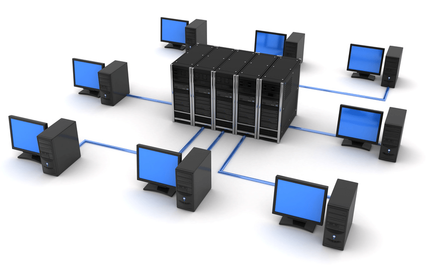
This is a parallel connection of devices to a network to a common source - a server. A hub or hub is most often used as a cent. All data is transferred through it. In this way, not only computers can work, but also printers, faxes and other equipment. In modern enterprises, this is the most frequently used method of organizing activities.

Advantages:
- Easy to connect one more site.
- Performance does not depend on the speed of individual elements, therefore it remains at a stable high level.
- Just find a breakdown.
Disadvantages:
- A malfunction of the central unit stops all users' activities.
- The number of connections is determined by the number of ports on the server device.
- The mesh consumes a lot of cable.
- Expensive equipment.
LAN software design stages
This is a multi-stage process that requires the competent participation of many specialists, since the necessary throughput cables, take into account the configuration of the premises, install and configure equipment.
Organization premises planning
You should arrange the offices of employees and superiors in accordance with the selected topology. If the shape of a star suits you, then it is worth putting the basic technique in that room, which is the main one and is located in the center. This could be the management's office. In the case of busbar distribution, the service can be located in the room farthest along the corridor.
Building a local network diagram

The drawing can be done in specialized computer-aided design programs. The products of the ZVSOFT company are ideal - they contain all the basic elements that are required for construction.
The grid should take into account:
- maximum voltage;
- sequence of entries;
- possible interruptions;
- economical installation;
- convenient power supply.
LAN characteristics must be selected in accordance with the organization's premises plan and the equipment used.
Parameters of computers and network devices
When choosing and purchasing mesh items, it is important to consider the following factors:
- Compatible with different programs and new technologies.
- Data transfer speed and speed of devices.
- The quantity and quality of cables depends on the selected topology.
- A method of managing exchanges in the network.
- Immunity to interference and failure by wire winding.
- The cost and power of network adapters, transceivers, repeaters, hubs, switches.
Principles of designing a LAN using computer programs
When drawing up a project, it is important to consider a large number of nuances. This will help the software from ZWSOFT. The company develops and sells multifunctional software for automating the work of design engineers. Basic CAD is an analogue of the popular but expensive package from Autodesk - AutoCAD, but surpasses it in ease and convenience of licensing, as well as in a more loyal pricing policy.

Benefits of the program:
- Intuitive, user-friendly interface in black.
- Wide range of tools.
- Work in two-dimensional and three-dimensional space.
- 3D visualization.
- Integration with files of most popular extensions.
- Organization of LAN elements in the form of blocks.
- Counting the lengths of cable lines.
- Visual arrangement of elements and nodes.
- Simultaneous work with graphics and text data.
- The ability to install additional applications.
For ZWCAD - a module that expands the functions of the basic CAD system in the design of multimedia circuits. All drawings are carried out with automated calculation of local area network cables and their marking.
Advantages:
- automation of selection of switching systems;
- wide library of elements;
- parallel filling of the cable magazine;
- automatic creation of specifications;
- adding equipment to the library;
- simultaneous work of several users with the database;
- schematic marks of the location of devices and pieces of furniture.
Will help to make a project in volumetric form, create it in 3D. Intelligent tools allow you to quickly lay LAN routes to connection points, visually represent the places where cables pass, organize line intersections, make cuts of connected equipment and technological furniture (including in dynamic mode). Using the component editor, you can create a library of cabinets, switching devices, cables, clamps, etc., as well as assign characteristics to them, on the basis of which you can later draw up specifications and calculations. Thus, the functions of this software will help to complete the general layout of the organization's premises with tracing of all LAN lines.
Create a project of a local area network in your enterprise together with programs from "ZVSOFT".
MINISTRY OF SCIENCE AND PROFESSIONAL EDUCATION
REPUBLIC OF SAKHA (YAKUTIA)
STATE EDUCATIONAL INSTITUTION
SECONDARY VOCATIONAL EDUCATION
NERUNGRINSKY HUMANITIES COLLEGE
Subject-cycle commission
"Mathematical disciplines and information technology"
COURSE WORK
Organization of a local area network at an enterprise
Norvaishas Sergey Evgenievich
4th year student
Full-time form of education
Specialty: 230105.51
"Software
computers and automated systems "
Leader: Khamrilova L.A.
Date of defense of the term paper:
"____" _______________ 2010
Grade: " "
Neryungri
Introduction 5
1.1. Purpose of packages and their structure 7
1.2. Exchange Control Methods 13
1.3. Traffic control in a star 15 network
Chapter 2. Networking Technology 18
2.1. Review and analysis of possible technologies for solving the task 18
Chapter 3. Designing an enterprise-wide network GOU SPO "Omsk College of Trade, Economics and Service" 22
3.1. Profile of the enterprise GOU SPO OKTEiS 22
3.2 Choosing network equipment 23
3.3 Brief description of the used network equipment 24
3.4 Choosing network software 25
3.4.1. Operating modes: 30
3.4.2 Installation and configuration 33
3.5. Schemes of the physical layout of the premises of OKTEiS 35
3.6. General scheme of the OKTEiS network 37
3.7. Theoretical and computational part 39
Conclusion 41
List of used literature 43
Introduction
If there are several computers in the same room, building or complex of nearby buildings, the users of which must jointly solve some problems, exchange data or use common data, then it is advisable to combine these computers into a local network.
A local network is a group of several computers connected by cables (sometimes also telephone lines or radio channels) used to transfer information between computers. Connecting computers to a local network requires network hardware and software.
The purpose of all computer networks can be summed up in two words: sharing (or sharing). First of all, I mean data sharing. People working on the same project have to constantly rely on data created by colleagues. Thanks to the local network, different people can work on the same project not in turns, but at the same time.
The local network provides the ability to share equipment. It is often cheaper to create a local network and install one printer for all departments than to purchase one printer for each workplace. The file server on the network allows you to share programs.
Hardware, software, and data are collectively referred to as resources. We can assume that the main purpose of a local network is access to resources.
The local network also has an administrative function. Monitoring the progress of projects on the network is easier than dealing with many stand-alone computers. If the classroom has a local network, then it also performs an administrative function, allowing you to monitor the progress of students' classes.
To communicate with external (peripheral) devices, the computer has ports through which it is able to transmit and receive information. It is easy to guess that if two or more computers are connected through these ports, they will be able to exchange information with each other. In this case, they form a computer network. If computers are located close to each other, use a common set of network equipment and are controlled by one software package, then such a computer network is called a local network. The simplest local area networks are used to serve workgroups. A working group is a group of people working on one project (for example, on the release of one magazine or on the development of one aircraft) or just employees of one department.
The aim of the course work is to design a local area network (LAN) for GOU SPO "Omsk College of Trade, Economics and Service" (OKTEiS).
To achieve the goal, the following tasks have been set:
analyze the methods of managing the exchange in the network;
review and analyze possible technologies for building a network;
choose network equipment and software for the LAN;
design general scheme College LAN;
Chapter 1. Packages, protocols and exchange control methods
Purpose of packages and their structure
Information in local networks, as a rule, is transmitted in separate chunks, chunks, called packets. Moreover, the maximum length of these packets is strictly limited (usually a few kilobytes). The length of the packet is also limited at the bottom (usually a few tens of bytes). The choice of bursting has several important considerations.
The local network, as already noted, must provide high-quality communication to all network subscribers. The most important parameter is the so-called access time, which is defined as the time interval between the moment the subscriber is ready to transmit (when he has something to transmit) and the moment the transmission starts. This is the time the subscriber waits for the start of his transmission. Naturally, it should not be too large, otherwise the value of the real, integral speed of information transfer between applications will greatly decrease even with high-speed communication.
Waiting for the start of transmission is due to the fact that several transmissions cannot occur simultaneously in the network (at least in the case of bus and ring topologies). There is always only one transmitter and one receiver (rarely, several receivers). Otherwise, information from different transmitters is mixed and distorted. In this regard, subscribers transmit their information in turn. And each subscriber, before starting the transfer, must wait for his turn. This waiting time for its turn is the access time.
If all the required information was transmitted by some subscriber at once, continuously, without dividing into packets, then this would lead to a monopoly seizure of the network by this subscriber for quite a long time. All other subscribers would have to wait for the end of the transfer of all information, which in some cases could take tens of seconds or even minutes (for example, when copying the contents of an entire hard disk). In order to equalize the rights of all subscribers, as well as to make approximately the same for all of them the value of the access time to the network and the integral speed of information transfer, packets of limited length are used.
Each packet, in addition to the actual data that needs to be transmitted, must contain a certain amount of service information. First of all, this is address information that determines from whom and to whom a given packet is transmitted.
Thus, the process of information exchange in the network is an interleaving of packets, each of which contains information transmitted from subscriber to subscriber.
Figure 1. Transmission of packets in the network between two subscribers.
In a particular case (Fig. 1), all these packets can be transmitted by one subscriber (when other subscribers do not want to transmit). But usually the network alternates packets sent by different subscribers (Fig. 2).

Figure 2. Transmission of packets in the network between several subscribers.
The structure and size of the packet in each network are strictly defined by the standard for this network and are associated, first of all, with the hardware features of this network, the selected topology and the type of information transmission medium. In addition, these parameters depend on the used protocol (order of information exchange).
But there are some general principles for forming the structure of the packet, which take into account the characteristic features of the exchange of information over any local area networks.
Most often, the package contains the following main fields or parts (Figure 3).
Figure 3. Typical package structure
A starting bit pattern or preamble that presets the adapter hardware or other network device to receive and process a packet. This field can be completely absent or reduced to a single start bit.
The network address (identifier) of the receiving subscriber, that is, an individual or group number assigned to each receiving subscriber in the network. This address allows the receiver to recognize a packet addressed to him personally, to the group he belongs to, or to all network subscribers at the same time (with broadcasts).
The network address (identifier) of the transmitting subscriber, that is, an individual number assigned to each transmitting subscriber. This address informs the receiving subscriber where the packet came from. The inclusion of the transmitter address in the packet is necessary when packets from different transmitters can alternately arrive at the same receiver.
Service information, which may indicate the type of packet, its number, size, format, route of its delivery, what the receiver needs to do with it, etc.
Data (data field) is the information for the transmission of which the packet is used. Unlike all other fields of the packet, the data field has a variable length, which, in fact, determines the total length of the packet. There are special control packages that do not have a data field. They can be thought of as network commands. Packages that include a data field are called information packets. Control packets can perform the function of starting and ending a communication session, acknowledging the receipt of an information packet, requesting an information packet, etc.
The checksum of a packet is a numerical code generated by the transmitter according to certain rules and containing information about the entire packet in a collapsed form. The receiver, repeating the calculations made by the transmitter with the received packet, compares their result with the checksum and makes a conclusion about the correctness or erroneousness of the packet transmission. If the packet is in error, then the receiver requests its retransmission. Typically a cyclic checksum (CRC) is used.
The stop combination serves to inform the equipment of the receiving subscriber about the end of the packet, provides the output of the receiver equipment from the receiving state. This field may be absent if a self-synchronizing code is used to determine when the packet has been transmitted.