Hard disk partitions and file systems. Basic concepts and basics of work
A hard disk drive (HDD) \\ HDD (Hard Disk Drive) \\ hard drive (media) is a material object that can store information.
Information storages can be classified according to the following criteria:
- information storage method: magnetoelectric, optical, magneto-optical;
- type of information carrier: drives on floppy and hard magnetic disks, optical and magneto-optical disks, magnetic tape, solid-state memory elements;
- the way of organizing access to information - drives of direct, sequential and block access;
- type of storage device - embedded (internal), external, stand-alone, mobile (wearable), etc.
A significant part of the information storage devices currently in use are based on magnetic media.
Hard disk device
 Winchester contains a set of plates, which are usually metal discs, covered with a magnetic material - platter (gamma ferrite oxide, barium ferrite, chromium oxide ...) and interconnected by a spindle (shaft, axle).
The disks themselves (approximately 2mm thick) are made of aluminum, brass, ceramics or glass. (see pic)
Both surfaces of the discs are used for recording. Used 4-9 plates... The shaft rotates at a high constant speed (3600-7200 rpm)
Rotation of discs and radical movement of heads is carried out using 2 electric motors.
Data is written or read using read / write headsone for each surface of the disc. The number of heads is equal to the number of working surfaces of all discs.
Information is recorded on the disk in strictly defined places - concentric tracks (tracks) ... The tracks are divided into sector.One sector contains 512 bytes of information.
The exchange of data between RAM and LMD is carried out sequentially with an integer (cluster). Cluster - chains of consecutive sectors (1,2,3,4, ...)
Special engine using a bracket, positions the read / write head over the specified track (moves it radially).
When the disc is turned, the head is positioned over the desired sector. Obviously, all heads move simultaneously and read information heads move simultaneously and read information from the same tracks of different information from the same tracks of different discs.
The tracks of the hard drive with the same serial number on different hard drives are called cylinder
.
The read / write heads move in along the surface of the platter. The closer the head is to the surface of the disc without touching it, the higher the permissible recording density.
Winchester device
Magnetic principle of reading and writing information

magnetic principle of information recording
The physical foundations of the processes of recording and reproducing information on magnetic media were laid in the works of physicists M. Faraday (1791 - 1867) and D. K. Maxwell (1831 - 1879).
In magnetic storage media, digital recording is made on a magnetically sensitive material. Such materials include some types of iron oxides, nickel, cobalt and its compounds, alloys, as well as magnetoplastics and magnetoelasts with viscous plastics and rubber, micropowder magnetic materials.
The magnetic coating is several micrometers thick. The coating is applied to a non-magnetic substrate, which distinguishes plastics for magnetic tapes and floppy disks, and aluminum alloys and composites for hard disks. The magnetic coating of the disk has a domain structure, i.e. consists of many small magnetized particles.
Magnetic domain (from Latin dominium - possession) is a microscopic, uniformly magnetized region in ferromagnetic samples, separated from neighboring regions by thin transition layers (domain boundaries).
Under the influence of an external magnetic field, the intrinsic magnetic fields of the domains are oriented in accordance with the direction of the magnetic field lines. After the termination of the action of the external field, zones of remanent magnetization are formed on the domain surface. Thanks to this property, information on the effect of the magnetic field is stored on the magnetic medium.
When recording information, an external magnetic field is created using a magnetic head. In the process of reading the information, the remanent magnetization zone, being opposite the magnetic head, induces an electromotive force (EMF) in it during reading.
The scheme for writing and reading from a magnetic disk is given in Fig. 3.1. The change in the direction of the EMF for a certain period of time is identified with a binary unit, and the absence of this change is identified with zero. The specified period of time is called bit element.
The surface of a magnetic medium is viewed as a series of dotted positions, each of which is associated with a bit of information. Because the location of these positions is imprecise, recording requires pre-printed marks to help locate the recording positions. To apply such synchronization marks, the disc must be divided into tracks
and sectors - formatting.
The organization of quick access to information on disk is an important stage of data storage. Online access to any part of the disk surface is provided, firstly, by giving it a fast rotation and, secondly, by moving the magnetic read / write head along the radius of the disk.
The floppy disk spins at 300-360 rpm, while the hard disk spins at 3600-7200 rpm.
The logical device of the hard drive
The magnetic disk is initially not ready for use. To bring it into working condition, it must be formatted, i.e. the disk structure must be created.
The structure (layout) of the disk is created during the formatting process.
Formatting magnetic disks includes 2 stages:
- physical formatting (low level)
- logical (high level).

Physical formatting splits the working surface of a disk into separate areas called sectors which are located along concentric circles - tracks.
In addition, sectors unsuitable for data recording are determined, they are marked as bad in order to avoid using them. Each sector is the smallest unit of data on the disk, has its own address to provide direct access to it. The sector address includes the side number of the disc, the track number, and the sector number on the track. The physical parameters of the disk are set.
As a rule, the user does not need to deal with physical formatting, as in most cases hard drives come in formatted form. Generally speaking, this should be done by a specialized service center.
Low-level formattingmust be done in the following cases:
- if there is a failure in track 0, which causes problems when booting from the hard disk, but the disk itself is available when booting from a floppy disk;
- if you are returning an old disk to working condition, for example, a disk that was moved from a broken computer.
- if the disk was formatted to work with another operating system;
- if the disk stopped working normally and all recovery methods did not give positive results.
Keep in mind that physical formatting is a very powerful operation - when it is executed, the data stored on the disk will be completely erased and it will be completely impossible to restore them! Therefore, do not start low-level formatting if you are not sure that you have saved all important data outside the hard drive!
After you perform low-level formatting, the next step follows - creating a partition of the hard disk into one or more logical drives - the best way to deal with the confusion of directories and files scattered around the disk.
Without adding any hardware elements to your system, you get the opportunity to work with several parts of one hard disk as with several drives.
This does not increase the capacity of the disk, but you can significantly improve its organization. In addition, different logical drives can be used for different operating systems.
When logical formatting
the final preparation of the medium for storing data occurs by the logical organization of disk space.
The disk is prepared for writing files to sectors created by low-level formatting.
After the disk partitioning table is created, the next stage follows - logical formatting of separate parts of the partition, hereinafter referred to as logical disks.
Logical disk - this is a certain area of \u200b\u200bthe hard disk that works in the same way as a separate drive.
Logical formatting is a much simpler process than low-level formatting.
In order to execute it, boot from the floppy disk containing the FORMAT utility.
If you have multiple logical drives, format them all sequentially.
During logical formatting, the disk is allocated system area, which consists of 3 parts:
- boot sector and partition table (Boot reсord)
- file allocation tables (FAT), in which the numbers of tracks and sectors that store files are recorded
- root directory (Root Direсtory).
Information is recorded in parts through the cluster. One and the same cluster cannot have 2 different files.
In addition, a name can be assigned at this stage.
A hard disk can be split into several logical disks and vice versa 2 hard disks can be combined into one logical one.
It is recommended to create at least two partitions on the hard disk (two logical disks): one of them is allocated for the operating system and software, the second disk is exclusively allocated for user data. Thus, data and system files are stored separately from each other and in the event of an operating system failure, it is much more likely to save user data.
Characteristics of hard drives
Hard drives (hard drives) differ from each other in the following characteristics:
- capacity
- speed - the time of access to data, the speed of reading and writing information.
- interface (connection method) - the type of controller to which the hard drive should be connected (most often IDE / EIDE and various SСSI variants).
- other features
1. Capacity- the amount of information that fits on the disk (determined by the level of manufacturing technology).
Today the capacity is 500-2000 GB or more. Hard disk space is never too much.
2. Speed \u200b\u200bof work (speed) disk is characterized by two indicators: disk access time and disk read / write speed.
Access time
- the time required to move (position) the read / write heads to the desired track and the desired sector.
The average characteristic access time between two randomly selected tracks is approximately 8-12ms (milliseconds), faster disks have a time of 5-7ms.
The transition time to an adjacent track (adjacent cylinder) is less than 0.5 - 1.5ms. It also takes time to turn to the desired sector.
The total disk turnover time for today's hard drives is 8-16ms, the average sector waiting time is 3-8ms.
The shorter the access time, the faster the disk will run.
Read / write speed (I / O bandwidth) or data rate (transfer) - the time of transferring sequentially located data depends not only on the disk, but also on its controller, bus types, processor speed. The speed of slow disks is 1.5-3 Mb / s, for fast drives - 4-5 Mb / s, for the most recent ones - 20 Mb / s.
Winchesters with SCSI-interface support the rotation frequency of 10000 rpm. and the average seek time is 5ms, the data transfer rate is 40-80 Mb / s.
3. Hard drive connection interface standard
- i.e. the type of controller to which the hard drive should be connected. It is located on the motherboard.
There are three main connection interfaces
- IDE and its various variants
IDE (Integrated Disk Electronics) or (ATA) Advanced Technology Attachment
Advantages - simplicity and low cost
Transfer rates: 8.3, 16.7, 33.3, 66.6, 100 Mb / s. As the data evolves, the interface supports the expansion of the list of devices: hard disk, super-floppy, magneto-optics,
NML, CD-ROM, CD-R, DVD-ROM, LS-120, ZIP.
Some elements of parallelization (gneuing and disconnect / reconnect), data integrity control during transmission are introduced. The main drawback of IDE is a small number of connected devices (no more than 4), which is clearly not enough for a high-end PC.
Today IDE interfaces have switched to the new Ultra ATA exchange protocols. Significantly increasing your bandwidth
Mode 4 and DMA (Direсt Memory Assess) Mode 2 allows data transfer at a speed of 16.6 Mb / s, but the actual data transfer rate would be much lower.
Ultra DMA / 33 and Ultra DMA / 66 standards, developed in February 98. by Quantum have 3 modes of operation 0,1,2 and 4, respectively, in the second mode the carrier supports
transmission speed 33Mb / s. (Ultra DMA / 33 Mode 2) This high speed can only be achieved by exchanging with the drive's buffer. In order to take advantage of
Ultra DMA standards must meet 2 conditions:
1.Hardware support on the motherboard (chipset) and from the drive itself.
2. to maintain the Ultra DMA mode, like other DMA (direсt memory Assess-direct memory access).
Requires special driver for different chipsets of different. As a rule, they are included with the motherboard, if necessary, you can "download"
from the Internet from the page of the manufacturer of the motherboard.
Ultra DMA is backward compatible with previous slower controllers.
Current version: Ultra DMA / 100 (Late 2000) and Ultra DMA / 133 (2001).
SATA
Replacing IDE (ATA) with no other Fireware high speed serial bus (IEEE-1394). The use of the new technology will allow to bring the transmission speed equal to 100Mb / s,
the reliability of the system is increased, this will allow installing devices without including a PC, which is absolutely impossible in the ATA interface.
SСSI (Small Сomputer System Interfaсe) - devices are 2 times more expensive than usual ones, they require a special controller on the motherboard.
Used for servers, publishing systems, CAD systems. Provide higher performance (speed up to 160Mb / s), a wide range of connected storage devices.
The SCSI controller must be purchased together with the corresponding disk.
SCSI advantage over IDE - flexibility and performance.
Flexibility consists in a large number of connected devices (7-15), and for IDE (4 maximum), a longer cable length.
Performance - high transfer rates and the ability to process multiple transactions at the same time.
1. Ultra Sсsi 2/3 (Fast-20) up to 40Mb / s 16-bit version Ultra2 - SСSI standard up to 80Mb / s
2. Another SCSI-interface technology called Fiber Channel Arbitrated Loop (FC-AL) allows you to connect up to 100 Mbps, while the cable length is up to 30 meters. The FC-AL technology allows you to perform "hot" connection, ie. on the go, has additional lines for error control and correction (technology is more expensive than conventional SСSI).
4. Other features of modern hard drives
The huge variety of hard drive models makes it difficult to choose the right one.
In addition to the required capacity, performance is also very important, which is determined mainly by its physical characteristics.
These characteristics are the average seek time, rotation speed, internal and external transfer rates, and the size of the cache memory.
4.1 Average search time.
The hard disk takes some time to move the magnetic head of the current position to a new one, required to read the next piece of information.
In each specific situation, this time is different, depending on the distance that the head must move. Usually, only averaged values \u200b\u200bare given in the specifications, and the averaging algorithms used by different companies are generally different, so that direct comparison is difficult.
For example, Fujitsu and Western Digital carry out all possible pairs of tracks, Maxtor and Quantum use the random access method. The result obtained can be additionally corrected.
The seek time value for writing is often slightly higher than for reading. Some manufacturers only give a lower value in their specifications (for reading). In any case, in addition to the average values, it is useful to take into account the maximum (through the entire disk),
and the minimum (that is, track to track) seek time.
4.2 Rotational speed
From the point of view of the speed of access to the desired fragment of the record, the rotation speed affects the value of the so-called latent time, which in order for the disk to turn to the magnetic head with the required sector.
The average value of this time corresponds to half a disk revolution and is 8.33 ms at 3600 rpm, 6.67 ms at 4500 rpm, 5.56 ms at 5400 rpm, 4.17 ms at 7200 rpm.
The latency value is comparable to the average seek time, so in some modes it can have the same, if not more, performance impact.
4.3 Internal baud rate
- the rate at which data is written to or read from disk. Due to the zone recording, it has a variable value - higher on the outer tracks and lower on the inner tracks.
When working with long files, in many cases it is this parameter that limits the transfer rate.
4.4 External baud rate
- rate (peak) with which data is transmitted through the interface.
It depends on the type of interface and most often has fixed values: 8.3; 11.1; 16.7Mb / s for Enhanced IDE (PIO Mode2, 3, 4); 33.3 66.6 100 for Ultra DMA; 5, 10, 20, 40, 80, 160 Mb / s for synchronous SСSI, Fast SСSI-2, FastWide SСSI-2 Ultra SСSI (16 bits), respectively.
4.5 Availability of the hard drive's own cache memory and its size (disk buffer).
The size and organization of the cache memory (internal buffer) can significantly affect the performance of the hard drive. As well as for regular Cache,
the performance gain slows down dramatically after reaching a certain volume.
Large Segmented Cache is useful for high performance SСSI drives used in multitasking environments. The more cache, the faster the hard drive (128-256Kb).
The impact of each parameter on overall performance is difficult to isolate.
Hard disk requirements
The main requirement for the disks is that the reliability of operation is guaranteed by the long service life of the components of 5-7 years; good statistics, namely:
- mean time between failures not less than 500 thousand hours (top class 1 million hours or more.)
- built-in system of active monitoring of the state of disk nodes SMART / Self Monitoring Analysis and Report Technology.
Technology S.M.A.R.T. (Self-Monitoring Analysis and Reporting Technology) is an open industry standard developed at the time by Compaq, IBM and a number of other hard disk manufacturers.
The essence of this technology lies in the internal self-diagnostics of the hard drive, which allows you to assess its current state and inform about possible future problems that could lead to data loss or drive failure.
Constant monitoring of the state of all vital disc elements is carried out:
heads, working surfaces, an electric motor with a spindle, an electronics unit. For example, if signal attenuation is detected, the information is overwritten and further observation occurs.
If the signal weakens again, then the data is transferred to another location, and this cluster is placed as defective and inaccessible, and instead of it another cluster from the disk reserve is provided.
When working with a hard disk, observe the temperature regime in which the drive is operating. Manufacturers guarantee trouble-free operation of the hard drive at ambient temperatures in the range from 0C to 50C, although, in principle, without serious consequences, you can change the boundaries of at least 10 degrees in both directions.
With large temperature deviations, an air gap of the required thickness may not form, which will lead to damage to the magnetic layer.
In general, HDD manufacturers pay quite a lot of attention to the reliability of their products.
The main problem is foreign particles getting inside the disk.
For comparison: a particle of tobacco smoke is twice the distance between the surface and the head, the thickness of a human hair is 5-10 times greater.
For the head, a meeting with such objects will result in a strong blow and, as a result, partial damage or complete failure.
Outwardly, this is noticeable as the appearance of a large number of regularly located unusable clusters.
Dangerous are short-term accelerations (overloads) of high modulus, arising from impacts, falls, etc. For example, from a blow, the head sharply strikes a magnetic
layer and causes its destruction in the appropriate place. Or, conversely, it first moves in the opposite direction, and then, under the influence of the elastic force, it is like a spring hitting the surface.
As a result, particles of a magnetic coating appear in the housing, which again can damage the head.
Do not think that under the action of centrifugal force they will fly away from the disk - the magnetic layer
will firmly attract them to itself. In principle, the consequences are not of the impact itself (you can somehow come to terms with the loss of a certain number of clusters), but the fact that in this case particles are formed, which will certainly cause further damage to the disk.
To prevent such very unpleasant cases, various firms have resorted to all sorts of tricks. In addition to simply increasing the mechanical strength of the disk components, intelligent S.M.A.R.T. technology is also used, which monitors the reliability of recording and data safety on the media (see above).
In fact, the disk is always not formatted to its full capacity, there is some margin. This is mainly due to the fact that it is almost impossible to make a carrier,
on which absolutely the entire surface would be of high quality, there will certainly be bad clusters (bad). When a low-level disk is formatted, its electronics are configured as
so that it bypasses these bad areas, and for the user it was completely unnoticeable that the media has a defect. But if they are visible (for example, after formatting
the utility displays their number other than zero), then this is already very bad.
If the warranty has not expired (and, in my opinion, it is best to buy an HDD with a warranty), then immediately take the disk to the seller and ask for a replacement media or a refund.
The seller, of course, will immediately begin to say that a couple of bad areas are not yet a cause for concern, but do not believe him. As already mentioned, this couple is likely to cause many more others, and subsequently a complete failure of the hard drive is generally possible.
The drive is especially sensitive to damage in working order, so you should not place the computer in a place where it can be subject to various shocks, vibrations, and so on.
Preparing the hard drive for work
Let's start from the very beginning. Let's assume that you bought a hard disk drive and ribbon cable separately from your computer.
(The fact is that when you buy an assembled computer, you will receive a disk prepared for use).
A few words about handling him. A hard disk drive is a very complex product containing, in addition to electronics, precision mechanics.
Therefore, it requires careful handling - shocks, falls and strong vibration can damage the mechanical part. As a rule, the drive board contains many small-sized elements and is not covered with sturdy covers. For this reason, you should take care of its safety.
The first thing to do after receiving a hard drive is to read the documentation that came with it - it will probably contain a lot of useful and interesting information. In this case, you should pay attention to the following points:
- the presence and options for installing jumpers that determine the configuration (installation) of the disk, for example, defining such a parameter as the physical name of the disk (they may exist, but they may not exist),
- the number of heads, cylinders, sectors on disks, the level of precompensation, and the type of disk. This information must be entered when prompted by the computer setup program.
All this information will be needed when formatting the disk and preparing the machine for working with it. - If the PC itself does not determine the parameters of your hard drive, installing a drive for which there is no documentation will become a bigger problem.
Most hard drives contain labels with the manufacturer's name, the type (brand) of the device, and also with a table of invalid tracks.
In addition, the drive can provide information about the number of heads, cylinders and sectors and the level of precompensation.
For the sake of fairness, it must be said that often only its title is written on a disc. But in this case, you can find the required information either in the reference book,
or by calling the representative office of the company. In doing so, it is important to get answers to three questions:
- how should jumpers be set in order to use the drive as master \\ slave?
- how many cylinders, heads on the disk, how many sectors per track, what is the precompensation value?
- what type of disk from the ROM BIOS is the best for this drive?
With this information in hand, you can proceed to install the hard disk drive.
To install a hard drive in your computer, do the following:
- Disconnect the system unit completely from the power supply, remove the cover.
- Connect the hard drive cable to the motherboard controller. If you are installing a second drive, you can use a flat cable from the first one if there is an additional connector on it, and you should remember that the speed of operation of different hard drives will be compared slowly aside.
- If necessary, change the jumpers according to the way of using the hard disk.
- Install the drive to a free space and connect the ribbon cable from the controller on the board to the hard drive connector with a red stripe to the power supply, power supply cable.
- Fasten the hard drive securely with four screws on both sides, neatly / span the cables inside the computer so that they do not cut them when closing the cover,
- Close the system unit.
- If the PC itself did not detect the hard drive, then change the computer configuration using Setup so that the computer knows that a new device has been added to it.
Winchester manufacturers
Winchesters of the same capacity (but from different manufacturers) usually have more or less similar characteristics, and the differences are expressed mainly in the case design, form factor (in other words, dimensions) and warranty period. And the latter should be said especially: the cost of information on a modern hard drive often exceeds its own price many times.
If your disk has malfunctions, then trying to repair it often means only exposing your data to additional risk.
A much more reasonable way is to replace the faulty device with a new one.
The lion's share of hard drives in the Russian (and not only) market is made up of products from IBM, Maxtor, Fujitsu, Western Digital (WD), Seagate, Quantum.
the name of the manufacturer producing this type of drive,
Corporation Quantum (www.quantum.com.), founded in 1980, is one of the veterans in the disk drive market. The company is known for its innovative technical solutions aimed at improving the reliability and performance of hard drives, access time to data on the disk and read / write speed on the disk, the ability to inform about possible future problems that could lead to data loss or disk failure.
- One of the proprietary Quantum technologies is SPS (Shock Protection System), designed to protect the disc from shock.
- built-in program DPS (Data Protection System), designed to save the most expensive - the data stored on them.
Corporation Western Digital (www.wd.сom.)is also one of the oldest disk drive companies, it has known its ups and downs in its history.
The company has recently been able to introduce the latest technologies into its discs. Among them, it is worth noting its own development-technology Data Lifeguard, which is a further development of the S.M.A.R.T. It attempts to logically end the chain.
According to this technology, the disk surface is regularly scanned during the period when it is not used by the system. In this case, the data is read and their integrity is checked. If problems are noted in the process of accessing a sector, the data is transferred to another sector.
Information about low-quality sectors is entered into an internal defect list, which makes it possible to avoid future writing to defective sectors in the future.
Firm Seagate (www.seagate.com) very well known in our market. By the way, I recommend the hard drives of this particular company as reliable and durable ones.
In 1998 she made a new comeback with her Medallist Pro series.
with a rotation speed of 7200 rpm, using special bearings for this. Previously, this speed was only used in SСSI drives, which increased performance. This series also uses the SeaShield System technology to improve the protection of the drive and the data stored on it from the effects of electrostatics and shock. At the same time, the effect of electromagnetic radiation is also reduced.
All manufactured disks support S.M.A.R.T.
Seagate's new drives include an improved version of its SeaShield system with more capabilities.
Significantly, Seagate claims the industry's highest shock resistance for the updated series, the 300G inoperative.
Firm IBM (www. Storage. Ibm. Com) although it was not until recently a major supplier in the Russian hard drive market, it quickly gained a good reputation for its fast and reliable hard drives.
Firm Fujitsu (www. Fujitsu.com) is a large and experienced manufacturer of disk drives, not only magnetic, but also optical and magneto-optical.
True, the company is by no means a leader in the market of hard drives with an IDE interface: it controls (according to various different studies) about 4% of this market, and its main interests lie in the field of SCSI devices.
Terminological dictionary
Since some of the drive elements that play an important role in its operation are often perceived as abstract concepts, the following is an explanation of the most important terms.
Access time - the period of time required by the hard disk drive to search and transfer data to or from memory.
The performance of hard disk drives is often determined by the access (access) time.
Cluster (Сluster) Is the smallest unit of space that the OS operates with in the file location table. Usually a cluster consists of 2-4-8 or more sectors.
The number of sectors depends on the type of disk. Searching for clusters instead of individual sectors reduces operating system overhead in time. Larger clusters provide faster performance
drive, since the number of clusters in this case is smaller, but the space (space) on the disk is used worse, since many files may be smaller than the cluster and the remaining bytes of the cluster are not used.
Controller (UU) (Сontroller) - circuits, usually located on an expansion board, that control the operation of the hard disk drive, including head movement and data reading and writing.
Cylinder - tracks located opposite each other on all sides of all discs.
Drive head - a mechanism that moves along the surface of a hard disk and provides electromagnetic recording or reading of data.
File Allocation Table (FAT) - a record generated by the OS, which keeps track of the placement of each file on the disk and which sectors are used and which are free to write new data to them.
Head gap - the distance between the drive head and the disk surface.
Interleave - the relationship between the speed of rotation of the disk and the organization of sectors on the disk. Typically, the rotation speed of the disk exceeds the computer's ability to receive data from the disk. By the time the controller reads data, the next serial sector has already passed the head. Therefore, data is written to the disk in one or two sectors. You can change the interleaving order when formatting a disc using dedicated software.
Logic drive - certain parts of the working surface of the hard disk, which are considered as separate drives.
Some logical drives can be used for other operating systems such as UNIX.
Parking (Park)- moving the drive heads to a certain point and fixing them in a motionless state over unused parts of the disk, in order to minimize damage when the drive is shaken when the heads hit the disk surface.
Partitioning - the operation of splitting a hard disk into logical disks. All disks are partitioned, although small disks can only have one partition.
Disc (Platter)- the metal disc itself, covered with a magnetic material, on which data is recorded. A hard drive usually has more than one drive.
RLL (Run-length-limited)Is a coding scheme used by some controllers to increase the number of sectors per track to accommodate more data.
Sector - the division of disk tracks, which is the basic unit of size used by the drive. OS sectors are usually 512 bytes.
Positioning time (Seek time)- the time required for the head to move from the track on which it is installed to any other desired track.
Track (Traсk)- concentric disc division. The tracks are like the tracks on a record. Unlike the tracks on a record, which are a continuous spiral, the tracks on a disc are circular. The tracks, in turn, are divided into clusters and sectors.
Track-to-track seek time - the time required for the drive head to move to an adjacent track.
Transfer rate- the amount of information transferred between the disk and the computer per unit of time. It also includes the track search time.
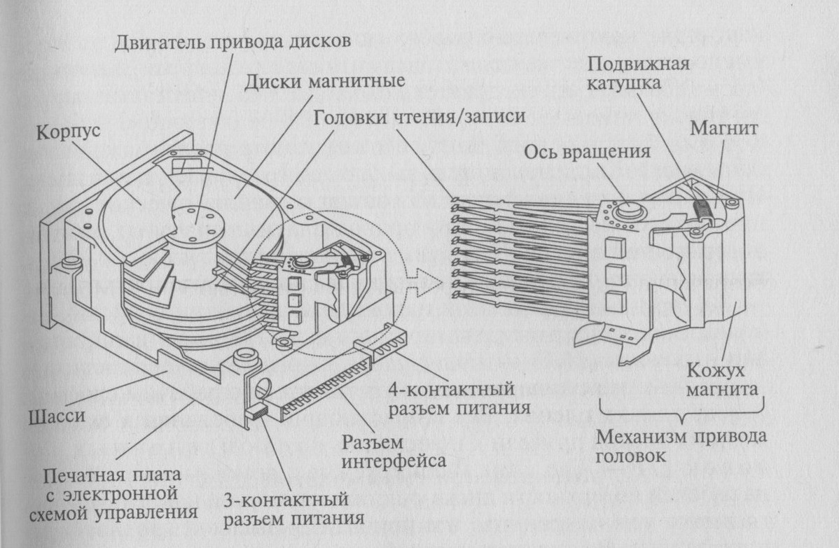
Any hard disk includes: a plate (pancake, mirror) covered with a thin layer of magnetic material, a head unit (BMG), a mechanism that ensures high-precision installation of the heads on the desired sector, the case and the microcontroller board. A mirror pancake (there may be several of them), on which the data is stored, is fixed to a rotating spindle. The heads always work in pairs - read and write. The positioning device is responsible for positioning the BMG relative to the surface of the magnetic plate. The case fixes all of the above elements and reliably protects them from external physical impact. The electronics board, on which the microcontroller is located, implements the functions of controlling the operation of all hard disk systems and is responsible for the two-way transport of information.
Hard drive geometry
Winchester plates can be cast from light metal alloys or ceramics. Each plane of the pancake (or working surface) is coated with a special magnetic substance, thanks to which the data is stored on the disk, and polished to a mirror finish. The composition of the feromagnetic material of each coating layer (layers, as a rule, several) is not the same and is a technological secret. Magnetic heads are located in the immediate vicinity of each working surface. To increase HDD performance, they always work in pairs, one for reading, the other for writing.
When formatting, a concentric notch is applied to the mirror, forming a kind of annular zones, which are called tracks. For convenience, each track with radii emanating from the center of the plate is divided into sectors (clusters). Any cluster consists of two conditional segments used to store service information and directly user data. The content of the service segment is formed once on the conveyor belt of the plant and is not subsequently rewritten. Among other things, the service segment contains the relative address of the entire sector on the surface of the plate. That is why the address is addressed to the cluster during read or write operations.
The clustered data segment is filled with information the user needs.
In other words, it stores pieces of those files that the owner of the drive writes to it. It is important to remember that the data segment of each sector cannot be overwritten in chunks. It will be updated completely, even if the size of the file copied to the hard drive is less than the allowed cluster data area.
In the case when a hard disk consists of several magnetic plates, experts are introducing another term into use - a cylinder. This word denotes a set of tracks located on different pancakes or adjacent working surfaces of one mirror and available for reading / writing without changing the position of the magnetic head unit. If we take into account that the positioning of the BMG does not occur instantaneously, then ideally located clusters of a single file should be located within one cylinder.
Initially, each track, regardless of its proximity to the center, was divided into a fixed number of clusters. This allowed the controller to address the sector by indicating only its number and cylinder number, as well as the head that needs to perform the operation. If we draw an analogy with a three-dimensional area, then a kind of cylindrical coordinate system was formed on the plate, where its angle (sector number), height (head number) and radius (cylinder number) were indicated to determine a point in space. Continuing the analogy to the Cartesian region of three dimensions, we come to a model of a multi-storey building, each apartment in which is similar to the previous one and is identified by a separate number.
The indicated arrangement of clusters practically three times reduced the recording density on the peripheral tracks, in relation to the inner ones. Taking into account this disadvantage, a new form of surface marking was developed, in which the number of clusters on a track increases with distance from the center of the plate. This form of information recording was called zone and made it possible to almost double the amount of useful information volume, without increasing the geometric dimensions of the pancake and the relative density of the recording on its surface.
The resulting markup is now much more difficult to represent in a Cartesian coordinate system, so a hard disk formatted in this way was not always correctly detected by the BIOS. This is due to the fact that not every interface is capable of correctly transforming the cluster structure so that it is understandable for the motherboard firmware. It is for this reason that several disk interfaces - ST506 / 412, ESDI and others - have gone out of use, and over time have been completely forgotten. With the introduction of the new layout geometry, only IDE and SCSI did not go away.
In fact, the procedure for transforming a chaotic circular structure into a neat 3D model is very similar to an insidious deception. For example, the BIOS limits the maximum number of sectors per track to 63; in reality, there are much more clusters. The interface deceives the BIOS by presenting it with a fake address structure in which there are exactly 63 sectors on a track. The same substitution occurs with the number of heads. For the convenience of addressing, their number varies in the range from 16 to 255 pieces, in fact, there are rarely more than 6. In the case of zone marking, the data exchange rate depends little on the proximity of the track to the center of the plate, its value will be more influenced by the cylinder number, in which contains clusters of information.
If you need, then contact us, we will help you with this problem.
ORGANIZATION OF HARD DISKS
|
Introduction 1. Organization of hard drives 1.1. Block devices 1.2. Hard drive device 1.2.1. Physical coordinates of HDD: cylinders, heads and sectors 1.2.2. Logic blocks 1.2.3. BIOS functions for hard drives 1.2.4. BIOS issues when dealing with large drives 2.3. Structural diagram of a hard disk 1.3.1. Block diagram of a physical device 1.3.2. Hierarchy of levels of abstraction of information presentation 1.4. Formatting hard drives 1.4.1. Physical formatting (low-level) 1.4.2. Boolean formatting 1.5. Sections 1.5.1. Primary Sections 1.5.2. Additional (extended) sections 1.5.3. Subsections of the additional section 1.5.4. Resize partitions. 1.6. File systems 1.6.1. FAT16 1.6.2. FAT32 1.6.3. NTFS 1.6.4. HPFS 1.6.5. Ext2fs 1.7. Mounting filesystems 1.7.1. Drive naming order 1.8. Operating system boot order 1.8.1. Master Boot Record (MBR) 1.8.2. OS Boot Block (BR) 1.9. Conclusion |
Introduction
The modern hard drive is a rather complex device. Modern trends towards an increase in the speed of reading and writing information, increasing the recording density, as well as meeting increased requirements for reliability, power consumption, and noise are achieved by the complication of technologies for organizing information storage and manufacturing technology for hard disk drives.
1. Organization of hard drives
1.1. Block devices
Any device for storing large amounts of information with the possibility of random access has onecharacteristic feature: Search time for information grows with increasing storage capacity. Due to this circumstance, it is convenient to split each data access operationin two stages
Finding the place where the information is on the media
Access to information
If the search phase is carried out by mechanical drive, then its execution time exceeds the time of reading or writing one byte by several orders of magnitude.
Therefore for improve work efficiency devices are made block-based: for each search operation, a sufficiently large chunk of data is read or written, which is called a block. Thus, access to information is carried out by arbitrarily addressable blocks, and the devices themselves are called block devices. Hard drives are a type of block device. Over time, the size of the information block has become the standard for all hard drives and is 512 bytes. For example, the number of blocks on a 40GB disk is about 80 million.
1.2. Hard drive device
A modern hard drive consists of one or more magnetically coated drives mounted on a rotating spindle. Magnetic heads move synchronously along each surface of each disk, providing information reading and writing. This entire system is controlled by built-in electronics, which ensures efficient transfer of information between the magnetic substance and the computer's memory.
1.2.1. Physical coordinates of HDD: cylinders, heads and sectors
At the physical level, the disk has three degrees of freedom to indicate the place (three coordinates) where information will be written or read:
Cylinder. When rotating discs with a magnetic coating, the heads move in a circle relative to the plates. Moreover, they are all at a certain distance from the center of the disk. The set of these circular head paths on all surfaces of the discs located at the same distance from the center is called a cylinder. Since the magnetic heads are rigidly connected to each other, they move synchronously and are simultaneously in the same cylinder. To install the heads on a given cylinder, it is necessary to set the head block in motion, which takes about 1.20 milliseconds.
Head. Several surfaces provide additional choice. It does not take any time to switch from one head to another, since the changeover is carried out without the involvement of mechanical components.
Sector. One block of information is a relatively small piece of data that geographically corresponds to a small arc of a circle. When viewed from the center, such arcs are located in one corner sector. Strictly speaking, this is not the case on modern discs, since the circumference increases with the radius, and the size of one bit is the same everywhere. Thus, the longer tracks fit more bits, and therefore more blocks of data. To select a sector on a track, you do not need to move the heads, but you need to wait for the platters to turn so that the sector address label approaches the read / write heads. At a disk rotation speed of about 5.7 thousand revolutions per minute, the waiting time for a sector turns out to be about 8-10 milliseconds. This time is even longer than the time of movement of the heads, however, after their movement, the sector label still has to be searched for, so changing the cylinder is the longest operation when searching for information.
The first hard drives had a relatively small number of cylinders, heads, and sectors and, in addition, did not have such a smart controller as today. Therefore, the blocks were addressed by specifying three numbers, cylinder, head and sector numbers, and these numbers corresponded to the physical organization of the data. Over time, this was not the case. Ondifferent cylinders located different number of sectors... Modern disk controllers themselves define some virtual disk geometry, which is reported to the computer. Therefore, the value of such a three-dimensional address indication is lost, and this method gradually dies out, leaving only compatibility problems.
Quite often you can hear it as the termblock and term sector ... Both indicate a 512 byte chunk of data when it comes to the hard disk. However, while the word “block” reflects the logical structure of data on the disk, the word “sector” reflects only part of the physical structure of the disks, which over time is increasingly hidden from us in the depths of the built-in controller. Hence it follows that it is more correct to use the wordblock.
1.2.2. Logic blocks
All modern hard drives have moved to a new, easier to use formaddressing - linear... Each block is characterized by a single number, its own number. Modern standardATA-5 allocates 28 bits for storing disk numbers, which allows to address 268435456 blocks, or approximately 137.4 Gigabytes.
The interpretation of the number is hidden in the built-in hard disk controller. Despite this, there is a common rule for hard drive manufacturers, according to which the logical block number is translated into cylinder, head and sector numbers:
<блок> = (<цилиндр> * NUMBER_HEADS +<головка>) * NUMBER_SECTORS +<сектор> - 1
NUMBER OF HEADS The number of hard drive heads returned by the BIOS
NUMBER_SECTORS Number of hard disk sectors returned by BIOS
<сектор> Sector number, from the range [1. NUMBER OF SECTORS]
<головка> Head number, from the range [0. NUMBER_HEADERS-1]
<цилиндр> Cylinder number, from the range [0. NUMBER_CYLINDERS-1]
Coordinate change sequence placing information in linear addressing: when increasing the block number, the sector number changes first, then the head number, then the cylinder number. This means that cylinders are the largest areas of contiguous data blocks. For this reason, cylinders are the boundaries to which partitions are aligned when they are created with most standard tools (fdisk).
Although linear addressing is more progressive, it ledto the appearance of problems with compatibilitywhich have been going on for several years. Basically, these problems relate to using new hard drives with old motherboards, as well as various BIOS settings, which will be discussed below.
1.2.3. BIOS functions for hard drives
The Basic Input / Output System (BIOS) allows programs to communicate with hard drives. There is a special software interrupt for this,INT 13h.
The main advantage of BIOS is that programs are provided with a standard interface for interacting with hard drives of any type. At the time when the first BIOS versions were designed, hard drives were not yet as well standardized as they are today, so the implementation of I / O functions was assumed to be different. Booting of operating systems (OS) occurs with the direct participation of BIOS at the initial stage, and for this reason, loading any OS starts in a standard way. This is also reflected in the positive role of BIOS.
The main disadvantages of BIOS with respect to working with disks are that these functions:
1. Too slow. The BIOS of most computers is very time consuming and repetitive. In addition, they do not always perform advanced diagnostics of hard drives, as a result of which the work with hard drives is not carried out in the most optimal modes from the point of view of performance. So, at modern read / write speeds of about 10 or more megabytes per second, the BIOS read speed is only 2-2.5 Mb / s.
2. Strictly consistent. One disk can only be accessed through the BIOS after access to another is complete, even though the devices themselves can function independently, thus reducing system efficiency.
3. They have only 20-bit memory addressing. BIOS functions were originally designed for Intel 8086 processors, which could only address 1 Megabyte of memory. Thus, the BIOS cannot fully realize the capabilities of a modern computer.
4. Have restrictions on the addressing of disk blocks, which leads to problems with loading OS located outside the 8GB border. Modern BIOS versions have an extension that helps solve this problem for modern operating systems. However, this extension is incompatible with older BIOS features, so older operating systems such as DOS that use older BIOS interfaces have not and will not be able to cross the 8GB limit.
Overcoming these shortcomings in modern operating systems is carried out using their own drivers for working with hard drives. However, at the initial stage, when the OS kernel is not yet loaded into memory and does not have drivers for working with disks, the BIOS provides the only unified way to boot the system.
BIOS functions provide access to drives by assigning unique numbers to them. For a disk number, 1 byte is allocated, which contains a number in the range 80-FFh (numbers 00h-7Fh correspond to a floppy disk). Within its settings, the BIOS names drives C, D, E., which correspond to numbers 80h, 81h, 82h,. These drive letters represent physical drives and should not be confused with logical drive letters as seen from operating systems.
1.2.4. BIOS issues when dealing with large drives
Standard BIOS functions operate on a disk solely in terms of cylinder, head, and sector. All parameters for read and write functions are transferred in processor registers, and
- 10 bits are assigned to the cylinder number (1024 cylinders).
-8 bits (256 heads) are assigned to the head number.
-Sector number is assigned 6 bits (63 sectors).
The first ATA standard for embedded hard disk controllers defined
the following ranges of parameters for hard drives:
-16 bits are assigned to the cylinder number (65536 cylinders).
-The number of the head is assigned 4 bits (16 heads).
-Sector number is allocated 6 bits (64 sectors).
As a result of the combined application of these requirements, the disk capacity addressed by the BIOS is limited to 504 MB. With the advent of larger disks, disk space usage issues have arisen. To solve these problems, different modes were implemented in the BIOS.broadcasts disk addresses.
NORMAL mode ... This is actually the mode in which only 504 MB is visible. In this mode, all values \u200b\u200bof the cylinder, head and sector numbers are transferred unchanged to the hard disk controller. This mode cannot be used with new discs due to the unavailability of most of the information.
LARGE mode ... This mode is an enhanced NORMAL mode. The BIOS converts the heads and cylinders, thereby changing the logical geometry of the disk. Since the number of heads available to the BIOS exceeds the maximum possible number of heads of the disk itself by 16 times, the BIOS reduces the number of logical cylinders by 2.4.8 times and at the same time increases the number of logical heads by the same number of times. It remembers the conversion factor, and with each access to the disk, immediately before generating a command to the controller, it does the reverse conversion. In this way, more blocks on the disk can be addressed using the transformation.
LBA mode ... In this mode, the linear block number is sent to the controller. Thanks to this, the BIOS does not have to adjust its logical geometry to some initial disk geometry, it simply does not exist. Therefore, the BIOS simply assigns the number of heads to 255, that is, the maximum possible value, which allows addressing up to 8GB.
Generally speaking, different modes are incompatible with each other if the software is tied to the number of sectors per track and the number of heads. Only linear addressing remains universal. For these reasons, it is highly discouraged to change the disk mode in BIOS settings after the disk is formatted. Otherwise, it may simply not be read.
2.3. Structural diagram of a hard disk
To use the hard disk more efficiently, you need to imagine its internal structure, the most useful aspects of which are the physical organization of the functional blocks of the disk and the levels of abstraction when presenting data.
If, when placing operating systems on a disk, take into account the peculiarities of its structure, then you can achieve higher performance of the file system, and, as a result, the entire system as a whole.
1.3.1. Block diagram of a physical device
The structural diagram of the hard disk is shown in the figure below. The central processor of the system communicates with the hard disk through standard interfaces for connecting high-speed peripheral devices. In modern hard disks, all control schemes for the processes of writing and reading information are concentrated in the built-in hard disk controller. The processor sends it commands to perform I / O operations, and the controller informs it about their execution by issuing an interrupt and returning the operation completion status.
Integrated controller fully controls the movement of heads, their parking, and the processes of recording information directly to magnetic disks. However, the disks themselves have rather poor dynamic characteristics, since the actuators and the spindle are mechanical parts, that is, very slow compared to electronics. Before the process of writing or reading to a magnetic platter begins, a rather long waiting time passes until the magnetic heads are above the recording location. This time can be two or three orders of magnitude longer than the recording time itself, so all modern discs are equipped with a special buffer memory.
Tasks buffer memory... With high bandwidth and ample storage capacity, it is capable of instantly absorbing sudden and infrequent disk writes. When positioning heads on a new track, modern controllers often begin to pre-read the entire track into the buffer memory, which allows you not to wait for slow mechanics on subsequent reads, since usually several adjacent disk blocks are most likely to be read. In addition, this memory can serve as a conventional disk cache, which is allocated from the amount of RAM to speed up disk access when multiple access to the same files.
Figure: 1 Structural diagram of a hard disk
The main factor that seriously slows down hard drive performance is head positioning. This process loads the CPU least of all.
Processor load during streaming reading without positioning is higher than with positioning. The exchange of information is weakened by positioning by two to three orders of magnitude. However, despite the unloading of the processor, in most applications this only leads to additional waiting for data. Therefore, it is logical to strive for such an organization of information on hard drives so that positioning is required as little as possible.
The tracks of a magnetic disk have different lengths, while the size of one bit of information on a magnetic disk has a constant length. The linear speed of rotation of the magnetic plates also differs on different tracks. Thus, start tracks farther from the center of rotation of the disc can accommodate more blocks than end tracks, and the read speed of these blocks will be the fastest.
For the same reason, positioning is less often required on the initial tracks. As a result, the average disk performance when working with its initial area will be higher than with the rest, so it is more profitable to place the most fastidious data in terms of performance on these tracks, for example, a partition for swapping, a partition with frequently called OS programs, etc.
1.3.2. Hierarchy of levels of abstraction of information presentation
With the development of operating systems and storage media, a multi-level system for organizing user data has developed. This is due to the introduction of open standards for hard disk controllers and their protocols for interacting with a computer, the complication of the structure of the data itself, the emergence of available RAID technology and other reasons. This section provides information on the various levels of abstraction.
The level diagram is shown in Figure 2 below.
Level 1 represents raw disk space that contains excess data blocks and is susceptible to bad ones. These are blocks placed directly on a magnetic medium. At this level, they have only their own address labels, but their continuous numbering is still impossible due to the fact that some of the blocks may be faulty. Work at this level is completely hidden in the hard disk controller and is not available to the user.
Level 2 is an addressable space of data blocks. At this level, the capacity of the disc corresponds to the capacity of the carrier declared in the device's passport. The addressable block space no longer contains bad blocks, so the blocks have unique linear numbers. These numbers are assigned to the hard disk controller for read / write operations. Typically, the addressable capacity of a disk is 70-90% of its raw capacity, based on platter area and storage density.
Level 3 is the address space of the hard disk, divided into non-overlapping partitions. Partitions are completely like a whole disk in that they are made up of contiguous blocks. Thanks to this organization, to describe a section, it is enough to indicate the beginning of the section and its length in blocks.
Partitioning of a disk is performed programmatically and is described using a partition table located in the first block of the hard disk. Sections at this level are real, physical sections, their addresses are addresses on a physical device.
Level 4 contains virtual partitions. Virtual partitions generalize the idea of \u200b\u200ba partition about a contiguous address space, but can be constructed from multiple physical partitions on one or more physical disks. In the operating system, such partitions are easily implemented using a simple filtering layer, which calculates the number of the block and disk that is actually being accessed from the logical block address in the virtual partition. In simple desktop systems, this level is simply absent (that is, all virtual partitions are always identical to physical partitions of level 3), but in systems using RAID technology, virtual partitions allow relatively cheap means to overcome the limitations of individual devices in terms of access speed and data storage reliability.
Level 5 contains file systems located in partitions. In almost all cases, a partition contains exactly one file system. The only exceptions are, perhaps, the swap partition, which has no file system at all, and an extended partition, which can contain multiple file systems. The first two levels. hardware, they are not available for the user to change. The rest of the levels are programmable.

Figure: .2 Layering hard drives
1.4. Formatting hard drives
To organize the storage of information, there are several levels of abstraction - disk layout (formatting). Distinguish between physical and logical formatting.
1.4.1. Physical formatting (low-level)
Physical formatting occurs at the first two levels of the disk hierarchy, described in Section 2.3.2, and consists of creating sector address labels on the disk, placing checksums and special synchronization fillers between sectors so that the controller itself can understand the bit stream coming from the disk. Users generally do not need to do low-level formatting, as this is done by manufacturers. The need for low-level formatting should not arise at all with proper disk operation. However, due to a possible imbalance of the heads, information loss is possible, and then low-level formatting can return the disk capacity.
The capacity of modern discs, and, accordingly, the recording density, is so large that it is very difficult to find an ideal magnetic platter that would not have defects. But even if such a plate were found, defects may arise during its operation. Making a plate with a larger capacity is much easier than making a plate without defects. For this reason, modern drives have built-in block forwarding tables and a dedicated spare block list. Reserved blocks are formatted in the same way as regular blocks, but do not have an explicit address for the end user of the computer. If the controller integrated into the disk detects an error while writing a certain block, then it redirects it to a new location selected from the reserve list. In this case, the backup unit receives the number of the unit that failed.
Modern hard drive controllers supportsMART technology , the essence of which is as follows. The controller keeps track of the number of forwarded blocks and the number of disk revolutions made since its start. Since the disc rotates at a constant speed, the number of revolutions is a unit of measure for the disc time (the disc has no built-in clock). Based on this data, you can estimate the rate of depletion of the reserve and make predictions about the moment of disk failure. Thus, the disk allows intelligent MTBF monitoring. The operating system can track the dynamics of changes in hard disk parameters and warn the user about a disk failure in advance, when the information can still be saved.
Although the use of spare blocks improves disk performance, remember that the spare block will only be used when the controller points to the failed block. In this case, in the case of recording, the loss of information will not occur, but in the case of reading, the missing information cannot be restored from the backup block. This will introduce potential errors at a higher level, file corruption, and possibly software crashes.
1.4.2. Boolean formatting
At a higher level, the disk must be logically formatted. Logical formatting occurs at level 5 of the hierarchy and consists in creating a file system, thereby achieving a higher organization of information. The files are named symbolically, allowing programs and users to structure information, search for information faster, and control the security of access to information.
Commonly called formatting is an operation performed by the format utility on DOS or Windows, or a utility such as dinit on UNIX. These utilities check the disk blocks for serviceability and, based on this data, create a map of free partition blocks suitable for storing information. In addition, they create a root directory and a so-called superblock, which contains all the necessary information needed to work with the file system. The superblock is usually located either in the very first block of the partition (along with the OS loader), or in another block, the position of which is fixed relative to the beginning of the partition. When the operating system is loaded, the file system driver reads the superblock into memory. Based on information taken from it, it calculates the location on disk of the root directory and all user data. Further calls to the disk are made by programs through the OS file subsystem.
During the formatting process, you can assign a symbolic name to the partition - a volume label. It serves to more easily identify a logical drive among the file system among other logical drives.
Logical formatting is applied to the disk partition. The file system created in the partition is usually identified with the partition itself. However, this is not quite true. The point is that information about the location of the partition on the disk is stored in the superblock, regardless of the partition table located in the MBR. When a superblock is created during formatting, information from the partition table about the position and length of the formatted partition is transferred to the superblock. This is due to the fact that the operating system takes all the data for working with the partition from the superblock, and not the partition table. Therefore, when changing the parameters of a partition in the table, the file system will not feel this change. Thus, the contents of the partition table may not correspond to the file system, if you think of it as a system of pointers to find the desired files or a new place to write new ones.
1.5. Sections
To organize operating systems, block disk address space is divided into parts called partitions. Partitions are completely like a whole disk in that they are made up of contiguous blocks. Thanks to this organization, to describe a section, it is enough to indicate the beginning of the section and its length in blocks. The level of physical partitions (level 3 in the hierarchy) arose in the course of historical development. The first hard drives had no partitions.
Hard disks were full analogs of floppy disks in that they contained only one file system. At the time, FAT12 was essentially the only file system for the PC. It was designed for only 4096 clusters, and was able to cover from 2 to 32 MB of disk address space, which soon led to problems because hard disks were constantly improving. The simplest way out in this situation was the invention of pseudophysical disks. sections. Each partition could contain one FAT12 file system. However, this required specifying for each partition its position on the disk and translating logical block addresses within the partition into absolute block addresses. We can judge the time of this transition by the complication of the superblock structure of FAT file systems. It happened somewhere since DOS 2.13, which corresponds, apparently, to the end of the summer of 1983.
Partition table. The emergence of partitions led to the invention of the partition table. A partition table describes up to four partitions on a disk. We placed this table in the very first block of the disk, since this was the only way to make it easily accessible during the boot process. After this complication of the structure, the first disk block was called the Master Boot Record (MBR - Master Boot Record).
Limiting the partition table to only four partitions has proven inconvenient over time. For this reason, the division of partitions into primary and extended sections has appeared. Today, partitioning a hard disk is a standard and mandatory procedure. Using disks without partitioning is not possible. The need to partition a disk into several partitions is due to the following reasons:
-Installing more than one OS on one hard drive;
-Increase the efficiency of using disk space;
-Manage the visibility of files for different users. (Protection from third-party users, viruses and program failures);
-Isolation of data of different kinds for easier and faster archiving and recovery.
Partitions are created by the fdisk program, the name of which is standard for almost all operating systems. For example utilities such asPartition Magic and SyMon contain their own creation and partitioning tools that go far beyond the capabilities of regular fdisk.
1.5.1. Primary Sections
Primary partitions are so named because their descriptors reside directly in the MBR. Primary partitions describe file systems as well as special swap partitions and additional partitions. The computer can boot only from primary partitions for all Microsoft systems and for most OS from other manufacturers.
1.5.2. Additional (extended) sections
An additional section is a primary section of a special kind. It does not directly contain the file system. Instead, it stores an extended partition table. The approximate topology is shown in the figure.

Figure: 3 Internal structure of extended partition
The first block of an extended partition contains a partition table similar to the MBR partition table (its format is exactly the same as in MBR, see section 2.8.1). The first entry in this table describes some subsection with respect to the position of this partition table itself, and the second does not describe the partition, but is an absolute reference (relative to the beginning of the entire disk) to the next extended partition table. Most system programs require:
-Each partition table was located in the first cylinder block.
-Each extended section table contained only one section descriptor and one link to the next extended section table.
-Each extended subsequent partition table was located further from the beginning of the disk than the previous one.
-The section described in the extended section table was located immediately after it, usually at the beginning of the next track.
Thus, an optional section describes the section chain that it contains entirely. However, this chain without the first section can be viewed as an extended section with fewer subsections without requiring any changes to the extended section tables immediately preceding the remaining subsections.
1.5.3. Subsections of the additional section
Subsections of the additional section are completely similar to the primary sections. They can contain filesystems and can be used for swapping. They cannot be completely aligned to the cylinder boundary, since they have an extended partition table in front of them, and the entire track is reserved for it. Therefore, they start at the first sector of the first track of the disc.
There is confusion between the extended partition subkeys and logical drives. The confusion comes from the fdisk utility. This utility creates subkeys inside the secondary partition and names them logical drives. However, a logical drive is a formatted partition containing the FAT, NTFS, or HPFS file system, that is, understood by the operating system. But not every subsection is obliged to contain just such a system.
1.5.4. Resize partitions.
Partition size is stored physically in two places:
- in the partition table, basic (MBR) or any extended.
- in the superblock of the file system.
Thus, the main challenge when resizing a partition is keeping those changes in sync. Resizing in just one place is not enough. The file system never adjusts to the size of the partition after it has been logically formatted. Files are always located in disk space, the length of which is specified in the superblock of the file system. Therefore, if the equality of the partition length values \u200b\u200bfrom the superblock and the partition table is violated, there is a danger that different file systems will overlap on the disk, and this, sooner or later, will lead to file corruption.
Resizing a formatted partition should be done using special programs. These programs understand the file system, diagnose whether the part of the partition to be deleted contains files, move them to another location, shorten or lengthen service structures such as FAT, MFT or inode. Only after the control structures of the file system are adapted to the new value of its size, this new value can be put in the superblock, and then in the partition table.
Changing an unformatted partition is much easier. Since there is no file system there, there is no superblock and all you need to do is change the values \u200b\u200bin the partition tables.
1.6. File systems
From the point of view of a hard disk, a file system should be understood as a system of partitioning a partition into service and user blocks for orderly storage of information. Service blocks describe the state of user blocks, which can be occupied by files or free. The tasks of the file system include:
-Manage the allocation of free blocks for new files
-Manage directories and filenames and links
- Search the contents of files by name.
Various file systems implement the listed functions with varying degrees of efficiency, and are also supported by different file systems. The most common file systems are listed below.
1.6.1. FAT16
This file system is one of the oldest systems still in use today. It is supported in most modern operating systems: DOS, Windows 95/98 / ME,Windows NT / 2000 / XP, OS / 2, Linux, QNX, FreeBSD and others.
The name of the file system comes from the name of its main control element. File Allocation Table. The data allocation unit is a cluster,. a collection of several contiguous disk blocks. The cluster size can be 1, 2, 4, 8, 16, 32 or 64 blocks. The files are chains of clusters. The file allocation table describes the chains of clusters belonging to each file. Each cluster can belong to at most one file.
The number 16 in the file system name indicates the number of binary bits allocated for storing the cluster number in the file allocation table. FAT16 allows up to 65525 clusters on a disk, the size of which can be from 512 to 32768 bytes. This allows you to create logical drives up to 2GB in size. The larger the disk size, the larger the required cluster size.
Generally speaking, large clusters reduce disk space efficiency. This is due to the fact that many files are short and some space in the cluster is lost. For greater reliability, two copies of the FAT are stored on the disk. Each change in file placement is reflected in both tables simultaneously. Mismatching these tables is an error. If there is a mismatch, then there is no proven way to determine which table contains more correct information. Therefore, the presence of two copies is justified only in the situation when one of the copies is simply not physically read from the disk. This situation is extremely unlikely for hard drives, and only possible for floppy disks. Indeed, the development of FAT systems began with the FAT12 system, which is still used today for floppy disks. In the case of floppy disks, the failure of a block belonging to one copy of the FAT has nothing to do with the failure of a block of the second copy, so the presence of two copies is justified. Any program error during FAT modification is usually reflected in both copies synchronously. In any case, if both copies of the FAT are properly read, there is a problem of choosing the correct copy.
The topology of the FAT16 file system is shown in Fig. 4.

Figure: 4 FAT16 partition topology
User clusters are located directly behind the root directory, which is sized during formatting and is not subsequently changed by the operating system.
1.6.2. FAT32
The FAT32 system is an evolution of the FAT system. The number of bits encoding the cluster number has been increased to 32. As a result, FAT32 is capable of containing almost 65,000 times more clusters than the FAT16 system. Even with a small cluster size, partitions up to 2TB can be formatted for this file system. Additionally, the FAT32 system has a boot record backup, and allows an arbitrary root directory location.
The FAT32 system is available for use starting from Windows 95 OEM Release 2, in Windows 98, ME, as well as in Windows 2000, XP. MS-DOS, Windows 3.1, Windows NT 3.51 / 4.0, earlier versions of Windows 95 cannot use FAT32.

Figure: 5 FAT32 partition topology
Unlike FAT16, FAT32 has the root directory in clusters like other files. The boot record contains a link to its first cluster.
1.6.3. NTFS
The NTFS file system is more complex than FAT systems. To work with it, more RAM is required, so its use begins to justify itself only on relatively productive systems that require high reliability. NTFS is used in Windows NT, Windows 2000 and Windows XP operating systems. It is not recommended to format partitions less than 400MB in size for NTFS, because a significant part of the space "disappears" for service data structures.
NTFS is based on a data structure called MFT (Master File Table). The MFT is also a system file that stores records of other files. Each file record has a fixed length. The record contains some fixed information common to all files, as well asfile attributes which describe the file name, location of its data, time and date of creation, etc. Each file is described by one number, which is an index in the MFT table.
Like FAT systems, NTFS is made up of clusters. However, there are several improvements over FAT. Clusters can be any power of 2 sector size, regardless of the partition size. Clusters fill the entire partition, that is, cluster 0 starts immediately at the beginning of the partition. Thus, the position of any cluster on the disk is uniquely calculated by the cluster number and its size.
The NTFS system allows encrypting files, storing them in a compressed form, journaling file operations, indexing files in directories by an arbitrary attribute, and not just by name. Finding a file in a directory is more streamlined than on FAT systems.

Figure: 6 NTFS partition topology
The disadvantage of NTFS is that the MFT is a vital structure, damage to which makes it completely impossible to recover files, even if they are not fragmented. The directory entry only refers to an MFT entry that contains the location of the file on disk as an attribute. The FAT system, although it is more primitive, allows the recovery of an unfragmented file from a directory entry that directly indicates the first cluster of the file and its size.
1.6.4. HPFS
This file system was developed by IBM and is a distant relative of NTFS. It is used primarily in the OS / 2 operating system and is also supported in earlier versions of Windows NT.
HPFS has better characteristics compared to FAT, directories are presented in a tree view, which allows you to quickly search for necessary files in large directories, as well as sort files by name. There are no clusters in this file system; free space is allocated sector by sector. The entire section is divided into 8MB sections, the free space in each section is described by a bitmap. This makes it easier to allocate space for files, since moving your head to the nearest bitmap, and not to the beginning of the disk, as in the FAT system.
1.6.5. Ext2fs
This file system is used as the main file system for Linux.
1.7. Mounting filesystems
Each file stored on disk has its own name. Knowing the name, users can work with the data contained in the file, pointing it to programs. Since files are usually arranged in an orderly manner in the form of a directory tree, or folders, then each file corresponds to a full name, indicating its position from the root of the tree. Each disk partition, formatted for a certain file system, contains a root directory and describes a portion of the future file system available to the user. For the operating system to find the user's files, it needs to provide the exact file name.
Thus, the file name consists of the name of its section, and its name within this section. This is true for any file system. For example, on a DOS system, to specify the exact location of the autoexec.bat file, specify C: \\ autoexec.bat. In this case, the name C: indicates the section, and the name \\ autoexec.bat. the name of the file inside it.
The operation of assigning a symbolic name to a partition containing a file system is called a mount. Mounting occurs at the start of the operating system, from this operation work with files begins.
Historically, mounting filesystems appeared on unix systems, where the filesystem was very flexible. The entire file system has one single root directory, and file names are not rigidly bound to specific physical devices. In addition, there is a paired unmount operation for mount operations. Both operations are available to the user during work, and not only at the start of the operating system. The user can define mount points by himself, so that the file names remain unchanged when the number of physical disks in the system changes. Moreover, even if in the process of changing the configuration of the computer the files become inaccessible or have changed names, the user can always unmount a part of the file system and mount it in the correct place in the file hierarchy.
Microsoft operating systems are not as flexible. File names do not start from a common root, but from the name of the drive on which they are located. The mount operation is performed by the system once at startup, and the mount point names, that is, the names of the disks, are assigned by the system in a rigid way, tied to the configuration of hardware devices. This creates a significant inconvenience in working with files, since almost any addition or removal of physical disks leads to changes in the mount points of the remaining disks without the user's knowledge.
Changing drive names often breaks paths to programs not located on the C: drive.
In Microsoft Windows NT / 2000 / XP systems, disks are mounted at computer startup, however, they allow reassignment of disk names, except for the boot disk. This allows some of the problems associated with changing the configuration to be avoided, although in practice it is rather inconvenient.
1.7.1. Drive naming order
When Microsoft operating systems are loaded, partitions (both primary and secondary subsections) act as carriers of logical disks, so the operating system assigns them alphabetic device names. Adding new hard drives to the system or removing existing ones affects the order in which letters are assigned to various logical drives, which often leads to undesirable effects.
The settings of many programs contain full paths to specific files, that is, they are tied to specific logical drives. If you change the drive letter names, the settings are incorrect, as a result of which it becomes impossible to work with the programs.
DOS, Windows 3.x, Windows 95/98 / ME, OS / 2
These operating systems assign drive names in a rigid manner based on the available drives and the types of partitions on them. The rules for assigning sections are as follows:
1. Names are assigned to all recognized active primary partitions, in the order of physical disks.
2. Names are assigned to all recognized disks located inside extended partitions. Extended partitions are iterated over in the order of physical disks.
3. Names are assigned to all remaining primary partitions, in the order of physical disks.
Thus, changing the number of physical disks can shift the letters assigned to logical disks. The shift of letters can also occur in the case of adding a deletion of a new section containing a file system recognized by this OS. Sections that contain a file system that the OS does not recognize are skipped by it, so there is no letter shift.
Windows NT / 2000 / XP
Initially, during the installation process, these operating systems behave similarly to the DOS & Windows 9x versions, with the difference that NTFS partitions are also recognizable for them. However, in the future, these systems allow reassigning the names of all disks, except for the one from which the system is booted. Reassigning disks is performed using the Disk Administrator utility included with Windows NT / 2000 / XP. After assigning disk names, they are assigned to their partitions and no longer depend on the appearance or deletion of other partitions.
1.8. Operating system boot order
Loading the operating system. multi-stage process. It starts in the BIOS after testing the hardware and determining the list of devices that support booting. These devices can be various disk drives, network adapters, tapes, and other devices. But first of all, hard drives are boot devices.
1. Select the disk from which to boot. The choice is made by the user in the BIOS setup during the general selection of the device from which to boot. In this case, the BIOS reassigns the disk numbers so that the boot disk is ranked first among all other disks.
2. The master boot record (MBR) is read from the selected disk. The signature is checked, which is responsible for the health of the read data. Control is transferred to the bootloader, which is part of the MBR. From this point on, boot control leaves the BIOS and is determined by the programs located on the hard drive.
3. The loader from the MBR detects the boot partition of the operating system. In the case of the standard MBR boot loader, the boot partition is the partition from the MBR partition table, marked with a special flag as the active partition. In the case of SyMon, the boot partition is specified by the user in the operating system settings. The boot sector of the operating system is read from the first block of the boot partition. The signature of this block is checked and, if successful, control is transferred to the bootloader located in it.
4. The operating system loader loads the operating system kernel and transfers control to the kernel.
5. After the kernel is initialized and the hard disk drivers are activated, the process of mounting and initializing file systems begins.
DOS).
These several stages are performed at different levels, which manifests itself, first of all, in compatibility problems. BIOS boot initially restricts all boot loader software to standard BIOS functions.
Given that bootloaders are allocated less than 512 bytes for their own functions, you can hardly expect them to be very flexible. The main difficulty lies in the fact that the bootloader does not have enough space to implement a mini-driver of the modern file system that could read the entire file into memory. Therefore, developers have to create a bootloader in two steps. On the first one, the bootloader located in the first block of the OS partition reads into the memory of the secondary bootloader, which is larger. The secondary loader already loads the kernel from a file.
1.8.1. Master Boot Record (MBR)
The master boot record is always located in block 0 of the physical disk and is essentially the boot sector of the hard disk as a whole. The MBR is always loaded by BIOS at memory address 0x0000: 0x7C00. The BIOS does not distinguish between the boot records of hard and floppy disks, although the former, unlike the latter, contain a partition table. An exception is, perhaps, the fact that in some modes the logical geometry of the disk (the number of heads and sectors) is adjusted according to the values \u200b\u200bof the MBR partition table. The main job of the BIOS with the MBR is to load and transfer control to the boot code.
Below is the structure of the MBR (a) and the structure of one partition in the partition table (b) of the boot record.

Figure: 7 Master boot record (MBR) format
1.8.2. OS Boot Block (BR)
The structure of the OS boot block, also called the boot record (Boot Record), can be arbitrary. Basically, two statements are true about boot blocks:
At the end of the boot block there is a signature 0xAA55, which is exactly the same as the MBR signature. This is due to their related origin,. BIOS practically does not distinguish between these blocks by purpose. Its main principle. download, check signature and run.
The OS boot block is always located in the very first block of the OS boot partition. The entry point to the loader program is always at address 0 relative to the beginning of the block. This gives the flexibility to boot any OS using the standard MBR boot loader.
The boot block contains a program that searches for and loads the OS kernel. However, since 512 bytes are clearly not enough to fit a serious program into them, there is a need for an intermediate loader, which:
1. Small enough to be easily loaded with a bootloader that is only 400-500 bytes in size.
2. Large enough to accommodate the file routines that search for and load the kernel.
There are two solutions to this problem, depending on the complexity of the file system.
The first is that the loader tries to read part of the operating system file right away. This is done, for example, by the DOS system and its successors - Windows 95/98 / ME. Their loader finds the IO.SYS file in the root directory and reads the first three blocks. The basis of this. the simplicity of FAT systems, which allows you to catch the beginning of the file from the disk using the first cluster of a file specified in a directory. However, system files must be defragmented and hidden from normal programs for this.
The second solution is that the loader contains in its body the absolute addresses of the continuation of itself and first of all reads its continuation into memory. This is done, for example, by ntldr, LILO and others. This solution is inconvenient in that the loader does not address itself through the file system, but directly, so manipulating the files can cause the download to fail, so you have to make it a non-relocatable file. But even if this is observed, moving the entire partition to a new location will again give an incorrect chain of blocks, and loading will become impossible. In such situations, it is always recommended to have a bootable floppy disk capable of restoring the OS bootloader to your hard drive.
1.9. Conclusion
This section covered the basic concepts related to the organization of information on hard drives. Any operating system is based on the principles outlined above.
Operating system installation begins with partitioning the disk. Further, partitions are formatted for one of the file systems supported by the operating system. After formatting, the disk space becomes available for storing files. The OS installer unpacks the software packages to the created free space. After that, it configures the programs and creates a boot record for the partition that loads the kernel after choosing this operating system.
Partitioning a disk is done programmatically using a data structure called a partition table. It resides in the very first block of the hard disk and is also called the Master Boot Record (MBR). The MBR contains records of 4 partitions, which may not be enough to install multiple operating systems if their number exceeds the number of free partitions. The standard MBR content allows you to boot operating systems from one of the 4 partitions described in the partition table. To boot more operating systems, special software is required to provide a boot menu and boot the user-selected operating system.
What does a modern hard disk drive (HDD) look like inside? How to take it apart? What are the parts called and what functions do they perform in the general information storage mechanism? The answers to these and other questions can be found here below. In addition, we will show the relationship between Russian and English terminology describing the components of hard drives.
For clarity, let's take a look at the 3.5-inch SATA drive. This will be a brand new terabyte Seagate ST31000333AS. Let's take a look at our guinea pig.
The green, screw-fastened plate with exposed traces, power and SATA connectors is called the Printed Circuit Board (PCB). It performs the functions of electronic control of the hard disk. Its work can be compared to putting digital data into magnetic prints and recognizing it back on demand. For example, as a diligent scribe with texts on paper. The black aluminum case and its contents are called the Head and Disk Assembly (HDA). Among specialists it is customary to call it a "bank". The case itself without content is also called HDA (base).
Now remove the PCB (you need a T-6 star screwdriver) and examine the components placed on it.

The first thing that catches your eye is the large chip located in the middle - System On Chip (SOC). It can be divided into two major components:
- The central processor that performs all calculations (Central Processor Unit, CPU). The processor has IO ports for controlling the rest of the PCB components and transferring data via the SATA interface.
- A read / write channel is a device that converts an analog signal from the heads to digital data during a read operation and encodes digital data into an analog signal during writing. It also performs tracking of head positioning. In other words, it creates magnetic images when writing and recognizes them when reading.
The memory chip is an ordinary DDR SDRAM memory. The amount of memory determines the size of the hard disk cache. This PCB has 32 MB Samsung DDR memory, which theoretically gives the disk a 32 MB cache (and this is the amount given in the hard disk specifications), but this is not entirely true. The point is that the memory is logically divided into buffer memory (cache) and firmware memory. The processor requires some memory to load firmware modules. As far as is known, only the manufacturer HGST indicates the actual cache size in the specification sheet; regarding the rest of the disks, the real cache size is anyone's guess. In the ATA specification, the compilers did not expand the 16 megabyte limit introduced in earlier versions. Therefore, programs cannot display more than the maximum volume.
The next chip is a spindle motor and voice coil controller that moves the head unit (Voice Coil Motor and Spindle Motor controller, VCM & SM controller). In the jargon of specialists, it is a "twist". In addition, this chip controls the secondary power supplies located on the board, from which the processor and the preamplifier (preamp) chip located in the HDA are powered. It is the main consumer of PCB energy. It controls spindle rotation and head movement. Also, when the power is turned off, it switches the stopping engine to the generation mode and supplies the received energy to the voice coil for smooth parking of the magnetic heads. The VCM controller core can operate even at temperatures as low as 100 ° C.
Part of the disk management program (firmware) is stored in flash memory (denoted in the figure: Flash). When power is applied to the disk, the microcontroller first loads a small boot-ROM inside itself, and then rewrites the contents of the flash chip into memory and starts executing the code from RAM. Without the correct code loaded, the drive won't even want to start the engine. If there is no flash chip on the board, then it is built into the microcontroller. On modern disks (sometime from 2004 and newer, but the exception is Samsung hard disks and they are also with stickers from Seagate) flash memory contains tables with codes for settings of mechanics and heads that are unique for this HDA and will not fit another. Therefore, the operation "toss the controller" always ends either with the fact that the disk is "not detected in the BIOS", or is determined by the factory internal name, but still does not give access to the data. For the Seagate 7200.11 drive under consideration, the loss of the original contents of the flash memory leads to a complete loss of access to information, since it will not be possible to pick or guess the settings (in any case, the author does not know such a technique).
On the R.Lab youtube channel, there are several examples of board swapping with re-soldering a microcircuit from a faulty board to a working one:
PC-3000 HDD Toshiba MK2555GSX PCB change
PC-3000 HDD Samsung HD103SJ PCB change
The shock sensor reacts to a shock hazardous to the disc and sends a signal to the VCM controller. The VCM will park the heads immediately and can stop the disc from spinning. In theory, such a mechanism should protect the disc from additional damage, but in practice it does not work, so do not drop discs. Even when falling, the spindle motor can jam, but more on that later. On some discs, the vibration sensor has increased sensitivity, reacting to the slightest mechanical vibrations. The data obtained from the sensor allows the VCM to correct head movement. On such disks, besides the main one, two additional vibration sensors are installed. On our board, additional sensors are not soldered, but there is space for them - they are designated in the figure as "Vibration sensor".
There is another protective device on the board - the Transient Voltage Suppression (TVS). It protects the board from power surges. In the event of a voltage surge, the TVS will burn out, creating a short to ground. This board has two TVSs, 5 and 12 volts.
The electronics for the older drives were less integrated, and each function was split into one or more chips.
Now let's look at the HDA.

Under the board are the contacts of the motor and heads. Besides, there is a small, almost imperceptible hole (breath hole) on the disk case. It serves to equalize the pressure. Many people think that there is a vacuum inside the hard drive. In fact, this is not the case. Air is needed for aerodynamic takeoff of the heads above the surface. This hole allows the disc to equalize the pressure inside and outside the containment. On the inside, this hole is covered with a (breath filter) filter that traps dust and moisture particles.
Now let's look inside the containment area. Remove the disc cover.

The lid itself is nothing interesting. It's just a steel plate with a rubber pad to keep out dust. Finally, consider the filling of the containment area.

Information is stored on disks, also called "pancakes", magnetic surfaces or platters. Data is recorded from both sides. But sometimes the head is not installed on one side, or the head is physically present, but disabled at the factory. In the photo you can see the top plate corresponding to the head with the highest number. Plates are made of polished aluminum or glass and are coated with several layers of various compositions, including a ferromagnetic substance, on which, in fact, the data is stored. Between the plates, as well as above the top of them, we see special inserts called dampers or separators. They are needed to equalize air flows and reduce acoustic noise. They are usually made of aluminum or plastic. Aluminum dividers cope better with air cooling inside the containment area. Below is an example of a model of air flow inside a HDA.

Side view of plates and separators.

The read-write heads (heads) are installed on the ends of the brackets of the magnetic head unit, or BMG (Head Stack Assembly, HSA). The parking zone is the area in which the heads of a healthy disc should be located if the spindle is stopped. On this disc, the parking zone is located closer to the spindle, as can be seen in the photo.

On some drives, parking is done on special plastic parking areas located outside the plates.

Parking area for Western Digital 3.5 "drive
If the heads are parked inside the plates, a special tool is needed to remove the magnetic head block; without it, it is very difficult to remove the BMG without damage. For outdoor parking, you can insert plastic tubes of suitable size between the heads and remove the block. Although there are also pullers for this case, but they are of a simpler design.
The hard disk is a precise positioning mechanism and requires very clean air to function properly. During use, microscopic particles of metal and grease can form inside the hard drive. There is a recirculation filter inside the disc to immediately clean the air. It is a high-tech device that continuously collects and traps the smallest particles. The filter is in the path of the air currents created by the rotation of the plates

Now let's remove the top magnet and see what is hidden under it.

Hard drives use very powerful neodymium magnets. These magnets are so powerful that they can lift 1,300 times their own weight. So don't put your finger between a magnet and a metal or other magnet - the impact will be very sensitive. This photo shows the BMG restraints. Their task is to limit the movement of the heads, leaving them on the surface of the plates. BMG limiters of different models are arranged in different ways, but there are always two of them, they are used on all modern hard drives. On our drive, the second stop is located on the lower magnet.
Here's what you can see there.

We also see a voice coil here, which is part of the magnetic head unit. The coil and magnets form the Voice Coil Motor (VCM) drive. The actuator and magnetic head assembly form an actuator - the device that moves the heads.
A black plastic part with a complex shape is called an actuator latch. It is of two types: magnetic and air (air lock). Magnetic works like a simple magnetic latch. The release is carried out by applying an electrical impulse. The air latch releases the BMG after the spindle motor has reached enough RPM for air pressure to push the latch out of the way of the voice coil. The latch protects the heads from flying out of the heads into the working area. If, for some reason, the latch did not cope with its function (the disc was dropped or hit while it was on), then the heads will stick to the surface. For 3.5 ”discs, subsequent switching on due to the higher power of the motor will simply tear off the heads. But the 2.5 "motor power is less and the chances of data recovery, freeing the native heads" from captivity ", are quite high.
Now let's remove the magnetic head assembly.

The precision and smoothness of the BMG movement is supported by a precision bearing. The largest part of a BMG, made of aluminum alloy, is usually called an arm or a rocker arm. At the end of the rocker there are heads on a spring suspension (Heads Gimbal Assembly, HGA). Usually the heads and rocker arms themselves are supplied by different manufacturers. Flexible cable (Flexible Printed Circuit, FPC) goes to a pad that mates with the control board.
Let's consider the components of the BMG in more detail.
A coil connected to a cable.

Bearing.

The following photo shows the contacts of BMG.

The gasket ensures the tightness of the connection. Therefore, air can only enter the disc / head assembly through the pressure equalization hole. This disc has a thin layer of gold plated contacts to prevent oxidation. But on the side of the electronics board, oxidation happens quite often, which leads to HDD malfunction. You can remove oxidation from the contacts with an eraser.

This is a classic rocker arm design.

The small black pieces at the ends of the spring hangers are called sliders. Many sources indicate that sliders and heads are one and the same. In fact, the slider helps to read and write information by raising the head above the surface of magnetic disks. On modern hard drives, the heads move at a distance of 5-10 nanometers from the surface. By comparison, a human hair is about 25,000 nanometers in diameter. If any particle gets under the slider, this can lead to overheating of the heads due to friction and their failure, which is why the purity of the air inside the containment area is so important. Dust can also cause scratches. They form new dust particles, but this time magnetic, which stick to the magnetic disk and cause new scratches. This leads to the fact that the disc is quickly covered with scratches or in the jargon "gash". In this state, neither the thin magnetic layer nor the magnetic heads work anymore, and the hard disk knocks (click of death).
The read and write head elements themselves are located at the end of the slider. They are so small that they can only be seen with a good microscope. Below is an example of a photograph (on the right) through a microscope and a schematic representation (on the left) of the relative position of the writing and reading elements of the head.

Let's take a closer look at the slider surface.

As you can see, the surface of the slider is not flat, it has aerodynamic grooves. They help stabilize the slider's flight height. The air under the slider forms an air cushion (Air Bearing Surface, ABS). The air cushion keeps the slider flight almost parallel to the pancake surface.
Here's another slider image.

The contacts of the heads are clearly visible here.
This is another important part of the BMG that has not been discussed yet. It is called a preamplifier (preamp). A preamplifier is a chip that controls the heads and amplifies the signal coming to or from them.

The preamplifier is placed directly in the BMG for a very simple reason - the signal coming from the heads is very weak. On modern drives, it has a frequency of over 1 GHz. If you move the preamplifier outside the containment area, such a weak signal will be greatly attenuated on the way to the control board. It is impossible to install the amplifier directly on the head, since it heats up significantly during operation, which makes it impossible for a semiconductor amplifier to work, vacuum-tube amplifiers of such small dimensions have not yet been invented.
More tracks lead from the preamplifier to the heads (right) than to the containment area (left). The fact is that a hard disk cannot simultaneously work with more than one head (a pair of writing and reading elements). The hard drive sends signals to the preamplifier, and it selects the head that the hard drive is currently accessing.
Enough about the heads, let's disassemble the disc further. Remove the upper separator.
This is what it looks like.

In the next photo you can see the containment with the top divider and head assembly removed.

The bottom magnet became visible.
Now the platters clamp.

This ring holds the block of plates together, preventing them from moving relative to each other.
Pancakes are strung on a spindle (spindle hub).

Now that nothing holds the pancakes, remove the top pancake. That's what's underneath.
![]()
Now it is clear why the space for the heads is created - between the pancakes there are spacer rings. The photo shows the second pancake and the second separator.
The spacer ring is a precision piece made from non-magnetic alloy or polymers. Let's take it off.
![]()
Let's pull out everything else from the disk to examine the bottom of the HDA.

This is what the pressure equalization hole looks like. It is located directly under the air filter. Let's take a closer look at the filter.
Since the air entering from the outside necessarily contains dust, the filter has several layers. It is much thicker than the circulating filter. Sometimes it contains silica gel particles to combat air humidity. However, if the hard drive is placed in water, it will be drawn in through the filter! And this does not mean at all that the water that gets inside will be clean. Salts crystallize on magnetic surfaces and sandpaper instead of plates is provided.
A little more about the spindle motor. Its construction is shown schematically in the figure.

A permanent magnet is attached to the inside of the spindle hub. The stator windings, by changing the magnetic field, cause the rotor to rotate.

Motors are of two types, with ball bearings and with hydrodynamic (Fluid Dynamic Bearing, FDB). Ballpoints were no longer used more than 10 years ago. This is due to the fact that they have a high beat. In a hydrodynamic bearing, the runout is much lower and it is much quieter. But there are also a couple of downsides. First, it can jam. Such a phenomenon did not happen with ball-shaped ones. If the ball bearings failed, they began to make a loud noise, but the information, though slowly, was readable. Now, in the case of a bearing wedge, it is necessary to remove all discs using a special tool and install them on a serviceable spindle motor. The operation is very complex and rarely results in successful data recovery. A wedge can arise from an abrupt change in position due to the large value of the Coriolis force acting on the axis and leading to its bending. For example, there are external 3.5 ”drives in a box. The box stood vertically, touched it, fell horizontally. It would seem that it did not fly far ?! But no - a wedge of the engine, and no information is available anymore.
Secondly, grease can leak out of the hydrodynamic bearing (it is liquid there, there is quite a lot of it, unlike the lubricant-gel used by ball bearings) and get onto the magnetic plates. To prevent the ingress of grease on magnetic surfaces, grease with particles that have magnetic properties and magnetic traps are used. An absorption ring is also used around the site of a possible leak. Overheating of the disk contributes to leakage, so it is important to monitor the operating temperature.
The clarification of the relationship between Russian and English terminology was carried out by Leonid Vorzhev.
Update 2018, Sergey Yatsenko
Reprinting or quoting is permitted provided the link to the original is preserved.
Hard drives, or, as they are also called, hard drives, are one of the most important components of a computer system. Everyone knows about it. But not every modern user even knows in principle how a hard drive functions. The principle of operation, in general, is quite simple for a basic understanding, but there are some nuances here, which will be discussed later.
Questions about the purpose and classification of hard drives?
The question of purpose is, of course, rhetorical. Any user, even the most entry-level one, will immediately answer that the hard drive (aka hard drive, aka Hard Drive or HDD) will immediately answer that it serves to store information.
In general, it is true. Do not forget that on the hard disk, in addition to the operating system and user files, there are boot sectors created by the OS, thanks to which it starts, as well as some labels by which you can quickly find the necessary information on the disk.
Modern models are quite diverse: ordinary HDDs, external hard drives, high-speed solid-state drives SSD, although they are not usually referred to as hard drives. Further, it is proposed to consider the device and principle of operation of a hard disk, if not in full, then at least in such a way that it would be enough to understand the basic terms and processes.
Please note that there is also a special classification of modern HDDs according to some basic criteria, among which the following can be distinguished:
- way of storing information;
- media type;
- way of organizing access to information.
Why is a hard drive called a hard drive?
Today, many users are wondering why they call them small arms hard drives. It would seem, what could be in common between these two devices?

The term itself appeared back in 1973, when the world's first HDD appeared on the market, the design of which consisted of two separate compartments in one sealed container. The capacity of each compartment was 30 MB, which is why the engineers gave the disk the codename "30-30", which was fully consonant with the brand of the popular 30-30 Winchester rifle at that time. True, in the early 90s in America and Europe this name practically fell out of use, but it still remains popular in the post-Soviet space.
The device and principle of operation of the hard disk
But we got distracted. The principle of operation of a hard disk can be briefly described as the processes of reading or writing information. But how does this happen? In order to understand how a magnetic hard disk works, you first need to study how it works.

The hard disk itself is a set of plates, the number of which can vary from four to nine, connected to each other by a shaft (axis) called a spindle. The plates are located one above the other. Most often, the materials for their manufacture are aluminum, brass, ceramics, glass, etc. The plates themselves have a special magnetic coating in the form of a material called platter, based on gamma ferrite oxide, chromium oxide, barium ferrite, etc. Each such plate is about 2 mm thick.
Radial heads are responsible for writing and reading information (one for each plate), and both surfaces are used in the plates. For which it can be from 3600 to 7200 rpm, and two electric motors are responsible for moving the heads.

In this case, the basic principle of the computer's hard disk is that information is not written anywhere, but in strictly defined locations, called sectors, which are located on concentric tracks or tracks. To avoid confusion, uniform rules apply. It means that the principles of hard disk drives, from the point of view of their logical structure, are universal. So, for example, the size of one sector, accepted as a unified standard all over the world, is 512 bytes. In turn, the sectors are divided into clusters, which are sequences of adjacent sectors. And the peculiarities of the principle of operation of a hard disk in this regard are that the exchange of information is exactly carried out by whole clusters (an integer number of chains of sectors).
But how does the reading of information take place? The principles of operation of a hard disk drive are as follows: using a special bracket, the read head moves in a radial (spiral) direction to the desired track and, when rotated, is positioned over a given sector, and all heads can move simultaneously, reading the same information not only from different tracks , but also from different disks (plates). All tracks with the same serial numbers are usually called cylinders.
At the same time, one more principle of hard disk operation can be distinguished: the closer the read head is to the magnetic surface (but does not touch it), the higher the recording density.
How is information written and read?
Hard drives, or hard drives, were called magnetic because they use the laws of physics of magnetism, formulated by Faraday and Maxwell.
As already mentioned, a magnetic coating is applied to the plates of a non-magnetically sensitive material, the thickness of which is only a few micrometers. During operation, a magnetic field appears, which has a so-called domain structure.
The magnetic domain is a magnetized region of the ferroalloy strictly limited by the boundaries. Further, the principle of operation of a hard disk can be briefly described as follows: when the effect of an external magnetic field occurs, the intrinsic field of the disk begins to orient itself strictly along the magnetic lines, and when the effect is terminated, zones of remanent magnetization appear on the disks, in which information that was previously contained in the main field ...
The reading head is responsible for creating an external field during writing, and when reading, the remanent magnetization zone, being opposite the head, creates an electromotive force or EMF. Then everything is simple: the change in the EMF corresponds to one in the binary code, and its absence or termination corresponds to zero. The time of EMF change is usually called a bit element.
In addition, a magnetic surface, purely for reasons of computer science, can be associated as a certain point sequence of information bits. But, since it is absolutely impossible to calculate the location of such points, it is necessary to install some predefined markers on the disk, which helped to determine the desired location. The creation of such labels is called formatting (roughly speaking, breaking the disk into tracks and sectors, combined into clusters).
The logical structure and principle of the hard disk in terms of formatting
As for the logical organization of the HDD, formatting comes first here, in which two main types are distinguished: low-level (physical) and high-level (logical). Without these stages, there is no need to talk about bringing the hard disk into working condition. How to initialize a new hard drive will be discussed separately.

Low-level formatting involves physical impact on the surface of the HDD, which creates sectors located along the tracks. It is curious that the principle of operation of a hard disk is such that each created sector has its own unique address, which includes the number of the sector itself, the number of the track on which it is located, and the number of the side of the plate. Thus, when organizing direct access, the same random access memory addresses directly to a given address, and does not look for the necessary information over the entire surface, due to which speed is achieved (although this is not the most important thing). Please note that when performing low-level formatting, absolutely all information is erased, and in most cases it cannot be restored.

Logical formatting is another matter (on Windows systems, this is quick formatting or Quick format). In addition, these processes are applicable to the creation of logical partitions, which are a kind of area of \u200b\u200bthe main hard disk that works in the same way.
Logical formatting primarily affects the system area, which consists of the boot sector and partition tables (Boot record), file allocation table (FAT, NTFS, etc.) and the root directory (Root Directory).
Information is recorded in the sectors through the cluster in several parts, and one cluster cannot contain two identical objects (files). Actually, the creation of a logical partition, as it were, separates it from the main system partition, as a result of which the information stored on it is not subject to change or deletion when errors and failures appear.
Main characteristics of HDD
I think, in general terms, the principle of the hard disk is a little clear. Now let's move on to the main characteristics, which give a complete picture of all the capabilities (or disadvantages) of modern hard drives.
The principle of operation of a hard disk and the basic characteristics can be completely different. To understand what we are talking about, let us single out the most basic parameters that characterize all information storage devices known today:
- capacity (volume);
- performance (speed of access to data, reading and writing information);
- interface (connection method, controller type).
Capacity is the total amount of information that can be recorded and stored on the hard drive. The HDD manufacturing industry is developing so rapidly that today hard drives with volumes of the order of 2 TB and more have come into use. And, as it is believed, this is not the limit.
The interface is the most significant characteristic. It determines exactly how the device is connected to the motherboard, which controller is used, how it reads and writes, etc. The main and most common interfaces are IDE, SATA and SCSI.
Disks with IDE-interface differ in low cost, but among the main disadvantages are the limited number of simultaneously connected devices (maximum four) and low data transfer rates (even if support for direct access to Ultra DMA memory or Ultra ATA protocols (Mode 2 and Mode 4) Although it is believed that their use can increase the read / write speed up to 16 Mb / s, but in reality the speed is much lower. In addition, to use the UDMA mode, you need to install a special driver, which, in theory, should be supplied in complete with motherboard.
Speaking about the principle of operation of the hard drive and its characteristics, one cannot ignore and which is the successor of the IDE ATA version. The advantage of this technology is that the read / write speed can be increased up to 100 MB / s using the high-speed Fireware IEEE-1394 bus.

Finally, the SCSI interface is the most flexible and the fastest in comparison with the previous two (read / write speed reaches 160 Mb / s and above). But such hard drives are almost twice as expensive. But the number of simultaneously connected storage devices is from seven to fifteen, the connection can be carried out without powering off the computer, and the cable length can be about 15-30 meters. Actually, this type of HDD is mostly used not in user PCs, but on servers.
Performance, which describes the transfer rate and I / O throughput, is usually expressed in transfer time and the amount of sequential data transferred, and is expressed in MB / s.
Some additional parameters
Speaking about what the principle of operation of a hard disk is and what parameters affect its operation, we cannot ignore some additional characteristics on which the performance or even the service life of the device may depend.
Here in the first place is the rotation speed, which directly affects the search and initialization (recognition) time of the desired sector. This is the so-called latent seek time - the interval during which the desired sector is rotated towards the read head. Today, several standards have been adopted for spindle speed expressed in rpm with dwell times in milliseconds:
- 3600 - 8,33;
- 4500 - 6,67;
- 5400 - 5,56;
- 7200 - 4,17.
It is easy to see that the higher the speed, the less time it takes to search for sectors, and in physical terms, to turn the disk before setting the required plate positioning point for the head.
Another parameter is the internal baud rate. On the outer lanes, it is minimal, but it increases with a gradual transition to the inner lanes. Thus, the same defragmentation process, which is moving frequently used data to the fastest areas of the disk, is nothing more than transferring it to an internal track with a faster read speed. The external speed has fixed values \u200b\u200band directly depends on the interface used.
Finally, one of the important points is related to the hard drive having its own cache memory or buffer. In fact, the principle of operation of a hard disk in terms of using a buffer is somewhat similar to RAM or virtual memory. The larger the cache memory (128-256 KB), the faster the hard drive will work.
Main requirements for HDD
There are not so many basic requirements that in most cases are imposed on hard drives. The main thing is long service life and reliability.
The main standard for most HDDs is considered to be a service life of about 5-7 years with an operating time of at least five hundred thousand hours, but for high-end hard drives this figure is at least a million hours.
In terms of reliability, the S.M.A.R.T self-test function is responsible for this, which monitors the state of individual elements of the hard drive, carrying out constant monitoring. On the basis of the collected data, even a certain forecast of possible malfunctions in the future can be formed.
It goes without saying that the user should not be left out. So, for example, when working with HDD, it is extremely important to observe the optimal temperature regime (0 - 50 ± 10 degrees Celsius), to avoid shocks, shocks and drops of the hard drive, dust or other small particles getting into it, etc. By the way, many will It is interesting to know that the same particles of tobacco smoke are approximately twice the distance between the read head and the magnetic surface of the hard drive, and the distance between a human hair is 5-10 times.
Initialization issues in the system when replacing the hard drive
Now a few words about what action to take if, for some reason, the user changed the hard drive or installed an additional one.

We will not fully describe this process, but will dwell only on the main stages. First, the hard drive must be connected and see in the BIOS settings whether the new hardware has been detected, in the disk administration section to initialize and create a boot record, create a simple volume, assign an identifier (letter) to it and format it with a choice of file system. Only after that the new "screw" will be completely ready for work.
Conclusion
That, in fact, is all that briefly concerns the fundamentals of the functioning and characteristics of modern hard drives. The principle of operation of an external hard drive was not considered in principle here, since it practically does not differ in anything from what is used for stationary HDDs. The only difference is the method of connecting the additional drive to your computer or laptop. The most common is the USB interface, which is directly connected to the motherboard. At the same time, if you want to ensure maximum performance, it is better to use the USB 3.0 standard (the port inside is colored blue), of course, provided that the external HDD itself supports it.
For the rest, I think, many have at least a little understood how a hard drive of any type functions. Perhaps, too much was given above, even more from the school course of physics, however, without this, it will not be possible to fully understand all the basic principles and methods inherent in the technologies of production and use of HDD.


