Powerful amplifier on TDA7294, assembled according to the ITUN scheme. Chip Amplifier TDA7294: Description, Datasheet and Examples of Low Frequency Amplifier on TDA7294
The article is dedicated to lovers of loud and high-quality music. TDA7294 (TDA7293) - Low frequency amplifier microcircuit produced by the French company Thomson. The scheme contains field transistorsthat provides high sound quality and soft sound. Simple schemeFew additive elements makes a scheme accessible to make any radio amateur. Right collected amplifier Of the serviceable parts begins to work immediately and in the setup does not need.

The sound frequency power amplifier on the TDA 7294 microcircuit differs from the other amplifiers of this class:
- high output power
- wide supply voltage range,
- low percentage of harmonic distortion,
- "soft sound,
- few "attached" details,
- low cost.
You can use in amplifier audio devices, when finalizing amplifiers, acoustic systems, audio devices, etc.
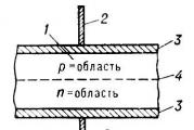
Figure below shows typical concept Power amplifier for one channel.


The TDA7294 chip is a powerful operational amplifier, the gain of which is set by the negative chain. feedbackincluded between its output (14 output. chips) and inversion input (out. 2 chips). The direct signal enters the input (out. 3 chips). The chain consists of R1 resistors and C1 condenser. By changing the resistance values \u200b\u200bR1, you can adjust the sensitivity of the amplifier under the pre-amplifier parameters.
Structural scheme amplifier on TDA 7294

Technical characteristics of the chip TDA7294
Technical characteristics of the chip TDA7293
Amplifier concept on TDA7294

For the assembly of this amplifier, the following details will be needed:
1. Microcircuit TDA7294 (or TDA7293)
2. Resistors with a power of 0.25 wool
R1 - 680 OM
R2, R3, R4 - 22 KOM
R5 - 10 KOM
R6 - 47 KOM
R7 - 15 KOM
3. Capacitor film, polypropylene:
C1 - 0.74 MKF
4. Electrolytic condensers:
C2, C3, C4 - 22 MKF 50 Volt
C5 - 47 MKF 50 Volt
5. Resistor Variable dual - 50 kom
On one microcircuit you can collect mono amplifier. To assemble the stereo amplifier, you need to make two boards. For this, all the necessary details are multiplied by two, except for a dual variable resistor and BP. But about this later.
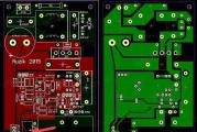
Printing fee of the amplifier on the TDA 7294 microcircuit
Installation of the scheme elements is made on a printing board from one-sided foil fiberglass.

Similar scheme, but slightly more elements, mostly capacitors. The inclusion delay circuit on the "MUTE" input is enabled. This is done for soft, without cotton, turning on the amplifier.


A microcircuit is installed on the board, which removed not using the conclusions: 5, 11 and 12. Putting the wire with a cross section of at least 0.74 mm2. The chip itself must be installed on a radiator with an area of \u200b\u200bat least 600 cm2. The radiator should not touch the enhancer body as it will be a negative supply voltage. The case itself must be combined with a common wire.
If you use a smaller area of \u200b\u200bthe radiator, you need to make a forced blowing, putting a fan into the amplifier housing. The fan will suit the computer, 12 volt voltage. The chip itself should be attached to the radiator using a heat-conducting paste. The radiator does not connect with the current-time parts except the negative tire. As mentioned above, the metal plate behind the microcircuit is connected to the negative supply chain.
Microcircuits for both channels can be installed on one common radiator.
Power supply for amplifier.
The power supply is a lower transformer with two windings with a voltage of 25 volts and a current force of at least 5 amps. The voltage on the windings should be the same and filter capacitors too. It is impossible to allow voltage skew. When filing two-polar power to the amplifier, it should be served simultaneously!

The diodes in the rectifier are better to put super-fast, but in principle they will fit and the usual type D242-246 per current of at least 10a. It is desirable parallel to each diode solder the capacitor with a capacity of 0.01 μF. You can also use ready-made diode bridges with the same current parameters.
C1 and C3 filter capacitors have a capacity of 22.000 μF per voltage 50 volts, C2 and C4 capacitors have a capacity of 0.1 μF.
The supply voltage of 35 volts should only be with a load of 8 ohms if you have 4 Ohm load, then the supply voltage must be reduced to 27 volts. In this case, the voltage on the secondary windings of the transformer must be 20 volts.
You can use two identical transformer with a capacity of 240 watts each. One of them serves to obtain a positive voltage, the second - negative. The power of two transformers is 480 watts, which is quite suitable for the amplifier with a 2 x 100 watt output.
TBS transformers 024 220-24 can be replaced by any other capacity of at least 200 watts each. As the power was written above should be the same - transformers should be the same !!! Voltage on the secondary winding of each transformer from 24 to 29 volts.
Amplifier scheme increased power On two TDA7294 chips on a bridge circuit.

According to such a scheme, four chips will need for a stereo version.
Technical characteristics of the amplifier:
- Maximum output power on the load of 8 ohms (PIT. +/- 25V) - 150 W;
- Maximum output power at a load of 16 ohms (PIT. +/- 35V) - 170 W;
- Load resistance: 8 - 16 ohms;
- Coef. Harmonic distortion, with max. Power 150 watts, for example. 25V, nation. 8 ohms, frequency of 1 kHz - 10%;
- Coef. harmonic distortion, with 10-100 watt power, for example. 25V, nation. 8 ohms, frequency of 1 kHz - 0.01%;
- Coef. Harmonic distortion, with 10-120 watt power, for example. 35V, Narch. 16 ohms, frequency of 1 kHz - 0.006%;
- Frequency range (with Ner. Ahh 1 dB) - 50Hz ... 100kHz.
View of the finished amplifier in a wooden housing with a transparent top cap from plexiglas.

To operate the amplifier in full power, you need to apply the required signal level to the input of the chip, and this is not less than 750mB. If the signal is not enough, then you need to collect a pre-amplifier for the swing.
Preliminary amplifier scheme on TDA1524A

Empowerment
The correctly assembled amplifier in establishing does not need, but no one guarantees that all the details are absolutely working, when you first turn on, care must be taken.
The first inclusion is carried out without load and with a disconnected input signal source (it is better to move the input of the jumper). It would be nice to the power circuit (and in the "plus" and in the "minus" between the power source and the amplifier itself) to include the fuses of order 1a. Briefly (~ 0.5 sec.) We supply the supply voltage and make sure that the current consumed from the source is small - the fuses are not burned. Convenient if there is a source lED indicators - When disconnected from the network, the LEDs continue to burn at least 20 seconds: the filter capacitors are long discharged by a small bowl of rest of the microcircuit.
If the current consumption of the current is large (more than 300 mA), then the reasons can be a lot: kz in montage; Bad contact in the "Earth" wire from the source; confused "plus" and "minus"; chip conclusions concern jumper; faulty microcircuit; Incorrect capacitors C11, C13; Faulty condensers C10-C13.
Making sure that the rest of the rest is fine, we boldly turn on the power and measure the constant voltage at the output. Its value should not exceed + -0.05 V. A great tension indicates problems with C3 (less often with C4), or with a microcircuit. There were cases when the "interground" resistor was either poorly propaigue, or instead of 3 ohms had a resistance of 3 com. At the same time, at the exit was the post 10 ... 20 volts. By connecting to the output voltmeter of AC, we make sure that the variable output voltage is zero (it is best to do with a closed input, or simply with a non-connected input cable, otherwise there will be no interference at the output). Availability at exit aC voltage Speaks about problems with microcham, or C7R9, C3R3R4, R10 chains. Unfortunately, often ordinary testers cannot measure high-frequency voltage, which appears during self-excitation (up to 100 kHz), so the oscilloscope is best used here.
Everything! You can enjoy your favorite music!
Full UH 2x70 Watt on TDA7294.
When assembling an amplifier on chips, TDA7294 is not a bad choice. Well, however, we will not stop on the technical characteristics, you can see them in PDF file. TDA7294_DataSheet located in a folder to download the material to build this UHC. As you already understood from the header of the article, this is a complete amplifier circuit that contains an input power supply, a signal pre-enhancement cascades with a three-band tone regulator, implemented on two common operational amplifiers 4558, two channel terminal cascades, as well as protection node. The schematic diagram is shown below:
With a supply voltage of ± 35 volts to the load of 8 ohms, you will receive 70 watts of power.
PCB source sources:


PCB LAY6 format:
Location of elements on the amplifier board:
Photo view of the Lay of the board format:
On the board there is a J5 connector for connecting the thermal sensor (Bimetal Thermostat), it is indicated by B60-70. In normal mode, its contacts are open, when heated to 60 ° C, the contacts are closed, the relay turns off the load. In principle, it is possible to apply thermo-sensors with normally closed contacts calculated on triggering at 60 ... 70 ° C, only to turn it on to break the emitter of the transistor Q6 and the common wire, while the j5 connector is not used. If you are not going to use this feature - leave the j5 empty connector.
Operating amplifiers are installed in panels. Relay on voltage 12 volts with two groups of switching contacts, contacts must withstand 5 amps.
Format Lay6 fuse printed circuit board:
Picture of Lay Format Format Fuses:
The power connector of the protection node is on the board just above the J5 connector. Just make a jumper with two wires between this connector and the main power connector as shown in the picture below:

External connections:
Additional Information:
4th - 2x18V 50Hz
8th - 2x24V 50Hz
With 2x18V 50Hz nutrition:
Resistors R1, R2 - 1 com 2W
Resistor RES - 150 Ohm 2W
When nutrition 2х24V 50Hz:
Resistors R1, R2 - 1.5 com 2W
Resistor RES - 300 Ohm 2W
JRC4558 operating amplifier can be replaced by NE5532 or TL072.
We draw your attention, from the side of the printed circuit board between the contacts of the relay coil, the Diode LL4148 is installed in the SMD version, the usual 1N4148 can be soldered.
Near the loudler regulator on the board there is a GND point, it is designed to ground the housings of all regulators. This segment of a naked copper wire is clearly visible on the main picture of the news.
List of elements for repeating amplifier circuit on TDA7293 (TDA7294):
Electrolytic capacitors:
10000mF / 50V - 2 pcs.
100mF / 50-63v - 9 pcs.
22mf - 5 pcs.
10mF - 6 pcs.
47mf - 2 pcs.
2,2mF - 2 pcs.
Capacitors Film:
1 MF - 8 pcs.
100n - 8 pcs.
6n8 - 2 pcs.
4n7 - 2 pcs.
22n - 2 pcs.
47N - 2 pcs.
100pf - 2 pcs.
47pf - 4 pcs.
Resistors 0.25W:
220r - 1 pc.
680r - 2 pcs.
1K - 6 pcs.
1K5 - 2 pcs.
3K9 - 4 pcs.
10K - 10 pcs.
20K - 2 pcs.
22K - 8 pcs.
30K - 2 pcs.
47K - 4 pcs.
220K - 3 pcs.
Resistors 0.5W:
Resistors 2 W:
RES - 300R - 2 pcs.
100R - 2 pcs.
Diodes:
Stabilians 12V 1W - 2 pcs.
1N4148 - 1 pc.
LL4148 - 1 pc.
1N4007 - 3 pcs.
Bridge 8 ... 10A - 1 pc.
Variable resistors:
A50K - 1 pc.
B50K - 3 pcs.
Microcircuits:
NE5532 - 2 pcs.
TDA7293 (TDA7294) - 2 pcs.
Connectors:
3x - 1 pc.
2x - 2 pcs.
Relay - 1 pc.
Transistors:
BC547 - 5 pcs.
LM7812 - 1 pc.
Download principal scheme Amplifier on TDA7294, TDA7294_Datasheet, Lay6 format printed circuit boards You can one file from our site. Archive size - 4 MB.
Article author: Novik P.E.
Introduction
The construct of the amplifier has always been a task not simple. Fortunately, in recent times, many integrated solutions appeared, facilitating the life of lovers to lovers. I also did not complicate the task and chose the simplest, high-quality, with a small number of details that do not require configuration and a steadily working amplifier on the TDA7294 chip from SGS-Thomson Microelectronics. Recently, the Internet has spread to this chip on the Internet, which were expressed in about the following: "spontaneously excited, with improper wiring; burns, for any occasion, etc.". Nothing like this. It is possible to burn it only to the wrong inclusion or closure, and the excitation cases were not observed, and not only with me. In addition, she has internal protection from short circuit In the load and overheating protection. It also implements the mute function (used to prevent clicks when turned on) and the standby function (when there is no signal). This ISS is an ungent class AV. One of the main features of this chip is the use of field transistors in preliminary and output enhanced cascades. Its advantages include a large output power (up to 100 W on the load of 4 ohm resistance), the ability to work in a wide range of supply voltages, high specifications (Small distortion, low noise, wide range of operating frequencies, etc.), minimum necessary external components and a small cost
The main characteristics of TDA7294:
Parameter |
Conditions |
Minimum |
Typical | Maximum | Units |
| Supply voltage | ± 10. | ± 40. | IN | ||
| Range of reproducible frequency | 3DB signal Output power 1W. |
20-20000 | Hz | ||
| Long term output power (RMS) | coeff harmonic 0.5%: UP \u003d ± 35 V, Rn \u003d 8 ohms UP \u003d ± 31 V, RN \u003d 6 ohms UP \u003d ± 27 V, Rn \u003d 4 ohms |
60 60 60 |
70 70 70 |
T. | |
| Peak musical output power (RMS), duration 1 sec. | coeff harmonic 10%: UP \u003d ± 38 V, RN \u003d 8 Ohm UP \u003d ± 33 V, RN \u003d 6 ohms UP \u003d ± 29 V, Rn \u003d 4 ohms |
100 100 100 |
T. | ||
| Common harmonic distortion | PO \u003d 5W; 1kHz PO \u003d 0.1-50W; 20-20000Gz |
0,005 |
0,1 |
% | |
| UP \u003d ± 27 V, Rn \u003d 4 ohms: PO \u003d 5W; 1kHz PO \u003d 0.1-50W; 20-20000Gz |
0,01 |
% | |||
| Security response temperature | 145 | 0 C. | |||
| Current in rest | 20 | 30 | 60 | ma. | |
| Input resistance | 100 | com | |||
| Voltage gain coefficient | 24 | 30 | 40 | dB | |
| Peak output current | 10 | BUT | |||
| Operating temperature range | 0 | 70 | 0 C. | ||
| Thermo resistance of the housing | 1,5 | 0 C / W | |||
(PDF format).
The inclusion schemes of this chip are quite a lot, consider the simplest:
Typical inclusion scheme:
List of items:
| Position | Name | A type | number |
| C1. | 0.47 μF. | K73-17 | 1 |
| C2, C4, C5, C10 | 22 μF x 50 b | K50-35 | 4 |
| C3. | 100 PF | 1 | |
| C6, C7. | 220 μF x 50 B | K50-35 | 2 |
| C8, C9. | 0.1 μF | K73-17 | 2 |
| DA1 | TDA7294. | 1 | |
| R1 | 680 Oh. | MLT-0.25 | 1 |
| R2 ... R4. | 22 com | MLT-0.25 | 3 |
| R5 | 10 com | MLT-0.25 | 1 |
| R6. | 47 com | MLT-0.25 | 1 |
| R7 | 15 com | MLT-0.25 | 1 |
The chip must be installed on a radiator with an area of\u003e 600 cm 2. Be careful, there is not a general one on the microcircuit housing, and minus power! When installing the chip on the radiator, it is better to use a thermal accelerant. It is advisable to pave between the microcircuit and the radiator of the dielectric (mica, for example). For the first time I did not give this importance, I thought, and from what such a fright I will closer the radiator on the body, but in the process of debugging the structure, inadvertently fallen from the table, the tweezers closed the radiator on the housing. The explosion was cool! The microcircuits simply spread into pieces! In general, got off with light fright and $ 10 :). On the boost with an amplifier, it is also desirable to supply powerful electrolytes 10000 mk x 50V to power, in order to give the power supply power from the power supply, the voltage failures did not allow. In general, the greater the capacity of the capacitors on the nutrition - the better, as they say, "do not spoil the porridge." Cap capacitor can be removed (or not to put), I did it. As it turned out, precisely because of it, when the volume controller (simple variable resistor is enhanced), an RC chain was obtained, which, with an increase in the volume, mowed high frequencies, and in general it is needed to prevent the amplifier excitation when the ultrasound is excited. Instead of C6, C7, I put on the board 10000 mk x 50V, C8, C9 you can put any close nominal - these are filters of power, they can stand in the power supply, and you can solder them by mounting, which I did.
Pay:
I personally do not like to use the finished fees, for one simple reason - it is difficult to find the same elements exactly the same in size. But in the wiring amplifier can greatly affect the sound quality, so you decide which fee to choose. Since I collected an amplifier at once on 5-6 channels, respectively, the fee at once on 3 channels:

In vector format (Corel Draw 12)
Power supply unit, Filter LF, etc.
Power Supply
For some reason, the power supply unit causes many questions. In fact, just here, everything is quite simple. Transformer, diode bridge and capacitors are the basic elements of the power supply. This is enough to build the simplest power supply.

To power the power amplifier, the stabilization of the voltage is unimportant, and the capacitors of power capacitors are important than - the better. The thickness of the wires from the power supply to the amplifier is also important.
My power supply is implemented by the following scheme:

Power + -15B is designed to power the operating amplifiers in the preliminary cascades of the amplifier. You can do without additional windings and diode bridges, drinking the stabilization module from 40B, but the stabilizer will have to guess a very large voltage drop, which will lead to a significant heating of stabilizer chips. 7805/7905 stabilizer chips - imported analogs of our roll.
Possible variations of blocks A1 and A2:

Block A1 is a filter for suppressing food interference.
Block A2 - block of stabilized stresses + -15V. The first alternative is easy to implement, for the nutrition of low-current sources, the second is a high-quality stabilizer, but requires an accurate selection of components (resistors), otherwise you will get a silent "+" and "-", which will then give zero skew on operating amplifiers.
Transformer
Power supply transformer for stereo amplifier 100wat should be approximately 200Wat. Since I did an amplifier on 5 channels, I needed a transformer more powerful. But I did not need to pump out all 100wat, and all channels cannot simultaneously select power. I got on the market Tesla transformer (below in the photo) Wat Edak on 250 - 4 windings with a wire of 1.5mm to 17V and 4 windings of 6.3V. By connecting them consistently, I received the necessary voltages, though I had to clear the two windings to 17B a little, in order to obtain the total voltage of the two windings ~ 27-30V, since the windings were on top of the work, this was not particularly.
Great thing - toroidal transformer, these are used to power the halogen in the lamps, in markets and shops are full. If constructively, two such transformers put one to another - the radiation will be mutually compensated for, which will reduce the fittings on the elements of the amplifier. The trouble is that they have one winding on 12V. We can make such a transformer on the Radiorenka, but it costs this pleasure decently. In principle, you can buy 2 transformers per 100-150vat and rewind secondary windings, the number of turns of the secondary winding will need to be increased by about 2-2.4 times.
Diodes / Diode Bridges
You can buy imported diode assemblies with a current of 8-12a, it greatly simplifies the design. I used pulse diodes CD 213, and did separately on the bridge on each shoulder to give a reserve for the diodes. When switching on, there is a charge of powerful capacitors, the current of the current is very significant, at a voltage of 40 V and the capacity of 10000 μF, the charge of such a capacitor is ~ 10 A, respectively, on two shoulders 20a. In this case, the transformer and rectifier diodes are briefly operating in short circuit mode. The test of diodes will give unpleasant consequences. Diodes were installed on radiators, but I did not find heating the diodes themselves - radiators were cold. To eliminate nutrition interference, it is recommended in parallel to each diode in the bridge, to install a condenser ~ 0.33mkp Type K73-17. I really did not do this. In the + -15B chain, you can apply the KC405 type bridges, for the current 1-2a.
Design


Finished design.
The most boried occupation is a hull. As a case, I took the old slim housing from the personal computer. I had to shorten it in depth, although it was not easy. I think that the case turned out to be successful - the power supply is in a separate compartment and you can still turn out to shove into the housing freely.

After field tests, it turned out that it was noterable to put fans on blowing radiators, despite the fact that radiators have very impressive sizes. I had to push the body from below and on top, for good ventilation. The fans are connected through the 100th 1.W Personnel Resistor to the smallest turns (see Figure Figure).
Amplifier block

Chips are on a mica and thermal paste, screws should also be isolated. Radiators and fees are screwed to the body through dielectric racks.

Entrance chains
I really wanted to do this, only in the hope that it is all temporary ....

After hanging out these gifts, a small buzz appeared in the speakers, apparently with the "earth" there was something wrong. I dream about that day when I throw it out of the amplifier and will use it only as a power amplifier.
Adverter Board, LF Filter, Folder

Block of regulation

Result
Rear it turned out beautiful, even though you will unfold him forward ... :)

The cost of construction.
| TDA 7294. | $25,00 |
| capacitors (powerful enetrolites) | $15,00 |
| condenters (others) | $15,00 |
| connectors | $8,00 |
| power button | $1,00 |
| diodes | $0,50 |
| transformer | $10,50 |
| radiators with coolers | $40,00 |
| resistors | $3,00 |
| variable resistors + handles | $10,00 |
| galenik | $5,00 |
| housing | $5,00 |
| operating amplifiers | $4,00 |
| surge Protectors | $2,00 |
| Total | $144,00 |
Yes, something happened to something. Most likely, something did not consider, it was just bought, as always, everything is much more, because I had to experiment, and I burned 2 chips and blew up one powerful electrolyte (I did not take into account all this). This is the calculation of the amplifier on 5 channels. As can be seen very weekly, radiators turned out, I used inexpensive, but massive coolers for processors, at that time (a year and a half ago) they were very good for cooling processors. If you consider that the initial level receiver can be bought for $ 240, then you can think about it - and whether you need it :), though there is an amplifier more low quality. Amplifiers of this class are about $ 500.
List of radio elements
| Designation | A type | Nominal | number | Note | Score | My notebook |
|---|---|---|---|---|---|---|
| DA1 | Audio amplifier | TDA7294. | 1 | In notebook | ||
| C1. | Capacitor | 0.47 Igf. | 1 | K73-17 | In notebook | |
| C2, C4, C5, C10 | 22 μF x 50 b | 4 | K50-35 | In notebook | ||
| C3. | Capacitor | 100 PF | 1 | In notebook | ||
| C6, C7. | Electrolytic condenser | 220 μF x 50 B | 2 | K50-35 | In notebook | |
| C8, C9. | Capacitor | 0.1 MKF. | 2 | K73-17 | In notebook | |
| R1 | Resistor | 680 Oh. | 1 | MLT-0.25 | In notebook | |
| R2-R4. | Resistor | 22 com | 3 | MLT-0.25 | In notebook | |
| R5 | Resistor |
Updated: 04/27/2016
An excellent amplifier for the house can be collected on the TDA7294 microcircuit. If you are not strong in electronics, then such an amplifier is the perfect option, it does not require fine tuning and debugging as a transistor amplifier and easy to build unlike the lamp amplifier.
The TDA7294 microcircuit is produced for the past 20 years and has not lost its relevance, and is still in demand in the circle of radio amateurs. For a novice radio amateur, this article will be a good help for acquaintance with integral sound frequency amplifiers.
In this article, I will try to write in detail the amplifier device on TDA7294. The main focus will be on the stereo amplifier collected by the usual scheme (1 microcircuit on the channel) and will briefly tell about the bridge circuit (2 microcircuits on the channel).
TDA7294 microcircuit and its features
TDA7294 - SGS-Thomson Microelectronics SGS-Thomson, this microcircuit is an AB class low frequency amplifier, and is built on field transistors.
Of the advantages of TDA7294, you can note the following:
- output power, when distorted 0.3-0.8%:
- 70 W for loading with 4 ohm resistance, ordinary scheme;
- 120 W for loading with an 8 ohm resistance, bridge circuit;
- mute function (MUTE) and standby function (STAND-BY);
- low noise level, small distortion, frequency range 20-20000 Hz, wide range of operating stresses - ± 10-40 V.
Specifications
| Technical characteristics of the chip TDA7294 | |||||
|---|---|---|---|---|---|
| Parameter | Conditions | Minimum | Typical | Maximum | Units |
| Supply voltage | ± 10. | ± 40. | IN | ||
| Range of reproducible frequency | Signal 3 db. Output power 1W. |
20-20000 | Hz | ||
| Long term output power (RMS) | coeff harmonic 0.5%: UP \u003d ± 35 V, Rn \u003d 8 ohms UP \u003d ± 31 V, RN \u003d 6 ohms UP \u003d ± 27 V, Rn \u003d 4 ohms |
60 60 60 |
70 70 70 |
T. | |
| Peak musical output power (RMS), duration 1 sec. | coeff harmonic 10%: UP \u003d ± 38 V, RN \u003d 8 Ohm UP \u003d ± 33 V, RN \u003d 6 ohms UP \u003d ± 29 V, Rn \u003d 4 ohms |
100 100 100 |
T. | ||
| Common harmonic distortion | PO \u003d 5W; 1kHz PO \u003d 0.1-50W; 20-20000Gz |
0,005 | 0,1 | % | |
| UP \u003d ± 27 V, Rn \u003d 4 ohms: PO \u003d 5W; 1kHz PO \u003d 0.1-50W; 20-20000Gz |
0,01 | 0,1 | % | ||
| Security response temperature | 145 | ° C. | |||
| Current in rest | 20 | 30 | 60 | ma. | |
| Input resistance | 100 | com | |||
| Voltage gain coefficient | 24 | 30 | 40 | dB | |
| Peak output current | 10 | BUT | |||
| Operating temperature range | 0 | 70 | ° C. | ||
| Thermo resistance of the housing | 1,5 | ° C / W | |||
Purpose of conclusions
| Appointment of the conclusions of the chip TDA7294 | |||
|---|---|---|---|
| Disclosure of the microcircuit | Designation | Purpose | Connection |
| 1 | STBY-GND. | "Signal Earth" | "General" |
| 2 | In- | Inverting input | Feedback |
| 3 | In +. | Unconforming input | Audio input through a separator capacitor |
| 4 | In + Mute. | "Signal Earth" | "General" |
| 5 | N.C. | Not used | – |
| 6 | Bootstrap | "Voltoddavod" | Capacitor |
| 7 | + VS. | Power supply input cascade (+) | |
| 8 | -VS. | Power supply input cascade (-) | |
| 9 | StBY. | Standby mode | Control block |
| 10 | Mute. | Mortulate mode | |
| 11 | N.C. | Not used | – |
| 12 | N.C. | Not used | – |
| 13 | + Pwvs. | Power supply Output Cascade (+) | Plus terminal (+) Power supply |
| 14 | Out. | Output | Audio output |
| 15 | -PWVS | Nutritional Cascade (-) | Minus terminal (-) power supply |
Note. The microcircuit body is associated with a minus power (conclusions 8 and 15). Do not forget about the insulation of the radiator from the amplifier housing or the insulation of the chip from the radiator by setting it through the thermal laying.
I also want to notice that in my scheme (as in the datashee) there is no separation of entrance and weekends "Lands". Therefore, in the description and the definition scheme, the "General", "Earth", "Corps", GND should be perceived as the concepts of one sense.
Difference in the housings
The TDA7294 microcircuit is produced by two species - V (vertical) and HS (horizontal). TDA7294V, having a classic vertical version of the housing, first sued a conveyor and to date is the most common and affordable.

Complex defense
The TDA7294 microcircuit has a number of protection:
- protection against supply voltage drops;
- protection of the output cascade from short circuit or overload;
- heavy protection. When heating the chip up to 145 ° C, the mute mode includes (MUTE), and at 150 ° C, the standby mode (STAND-BY) is turned on;
- protection of chip conclusions from electrostatic discharges.
Power amplifier on TDA7294
Minimum details in the strapping, simple printed circuit board, patience and obviously suitable details will allow you to easily collect inexpensive UMPs on TDA7294 with clean sound and good power for home use.
You can connect this amplifier directly to linear output. sound card Computer, because Nominal input voltage of an amplifier 700 mV. And level nominal tension The linear output of the sound card is regulated in the range of 0.7-2 V.
Structural scheme amplifier

The diagram is presented with an option stereo amplifier. The structure of the amplifier on the pavement scheme is similar - also two boards with TDA7294.
- A0.. Power Supply
- A1.. Mute and Stand-BY modes control unit
- A2.. Umzch (left channel)
- A3.. Umzch (Right Channel)
Pay attention to the connection blocks. Incorrect wiring of wires inside the amplifier can cause additional interference. To minimize noise, follow the shortest rules:
- Power to each boost of the amplifier must be inserted by a separate harness.
- Power wires must be a pigtail suite (harness). This will allow to compensate for the magnetic fields created by the current flowing. We take three wires ("+", "-", "common") and weave the pigtail made of them with a light tension.
- Avoid "earth loops". This is such a situation when a common conductor, connecting blocks, forms a closed circuit (loop). Connecting a common wire should go sequentially from the input connectors to the volume control, from it to the UMP card and on the output connectors. It is advisable to use isolated from the housing connectors. And for the input chains also shielded wires in isolation.
List of parts for BP TDA7294:

By purchasing a transformer, note that the active voltage value is written on it - u d, and, measuring the voltmeter, you will also see the active value. At the exit after rectifying bridge, capacitors charge to amplitude voltage - u A. Amplitude and active stresses are associated with the following dependence:
U a \u003d 1.41 × u d
According to the characteristics of TDA7294 for the load of 4 ohms, the optimal supply voltage is ± 27 volts (U a). The output power with such voltage will be 70 W. This is the optimal power for TDA7294 - the level of distortion will be 0.3-0.8%. Increase power to increase power No sense because The level of distortion is growing avalanche-like (see chart).

Calculate the required voltage of each secondary transformer winding:
U d \u003d 27 ÷ 1.41 ≈ 19 V
I have a transformer with two secondary windings, with a voltage on each winding of 20 volts. Therefore, in the diagram I designated the power terminals as ± 28 V.
To obtain 70 W per canal, considering the CPD of the chip 66%, we consider the power of the transformer:
P \u003d 70 ÷ 0.66 ≈ 106 VA
Accordingly, for two TDA7294 is 212 VA. The nearest standard transformer, with a margin, will be 250 VA.
It is appropriate to state that the power of the transformer is counted for a clean sinusoidal signal, for real musical sound there are amendments. So, Igor Rogov claims that for an amplifier with a capacity of 50 W, there will be enough transformer on 60 VA.
The high-voltage part of the BP (to the transformer) is collected on a printed circuit board of 35 × 20 mm, and mounted mounting:

The low-voltage part (A0 according to the structural scheme) is collected on the printed circuit board 115 × 45 mm:

All amplifier boards are available in one.
This power supply for TDA7294 is designed for two microcircuits. For more chips, you will have to replace the diode bridge and increase the capacitance capacitors, which will entail a change in the size of the board.
Mute and Stand-BY modes control unit
The TDA7294 chip has a standby mode (STAND-BY) and a mute mode (MUTE). Control by these functions occurs through the conclusions 9 and 10, respectively. The modes will be turned on. While there is no voltage at these outputs or it is less than +1.5 V. To "wake up" the chip sufficiently submit to the conclusions 9 and 10 voltage more than +3.5 V.
For the simultaneous management of all CLEAT fees (especially relevant for bridge circuits) and saving radio components there is a reson to collect a separate control unit (A1 by structural scheme):

List of parts for control unit:
- Diode (VD1). 1N4001 or similar.
- Capacitors (C1, C2). Polar electrolytic, domestic k50-35 or imported, 47 μF 25 V.
- Resistors (R1-R4). Ordinary low-power.
The block circuit board has a size of 35 × 32 mm:

The task of the control unit to ensure a silent inclusion and turn off the amplifier due to Stand-BY and MUTE modes.
The principle of work is next. When the amplifier is turned on, together with the power supply condensers, the C2 control unit is charging. As soon as it charges, Stand-by will turn off. A slightly longer charges the capacitor C1, so the MUTE mode will turn off in the second line.
When the amplifier is disconnected from the network, the C1 capacitor via the VD1 diode is discharged and includes MUTE mode. Then the C2 condenser is then discharged and sets the STAND-BY mode. The microcircuit shuts when the power supply capacitors have a charge of about 12 volts, so no clicks and other sounds are heard.
Amplifier on the TDA7294 on the usual scheme
The inclusive chip on the inclusion circuit, the concept corresponds to the original from the datashet, only the nominal components are changed to improve sound characteristics.
List of parts:
- Condensers:
- C1.. Film, 0.33-1 μF.
- C2, C3.. Electrolytic, 100-470 MKF 50 V.
- C4, C5.. Film, 0.68 μF 63 V.
- C6, C7.. Electrolytic, 1000 μF 50 V.
- Resistors:
- R1. Variable dual with a linear characteristic.
- R2-R4.. Ordinary low-power.
Resistor R1 dual because Stereo amplifier. Resistance not more than 50 com from linear, and not logarithmic characteristic for smooth volume adjustment.
The R2C1 circuit is the top frequency filter (PVCH), suppresses the frequency below 7 Hz, not missing them to input the amplifier. Resistors R2 and R4 must be equal to ensuring the stable operation of the amplifier.
Resistors R3 and R4 organize a negative feedback circuit (OOS) and specify the gain:
Ku \u003d R4 ÷ R3 \u003d 22 ÷ 0.68 ≈ 32 dB
According to the datashet, the gain coefficient must lie within 24-40 dB. If less, the microcircuit will be self-excitement, if more - distortion will grow.
C2 capacitor is involved in the OOS circuit, it is better to take with a greater capacity to reduce its effect on low frequencies. C3 condenser provides an increase in the supply voltage of the output cascades of the chip - "Voltoddavod". Capacitors C4, C5 eliminate the vendors introduced by wires, and C6, C7 complement the capacity of the filter of the power supply filter. All capacitors of the amplifier, except C1, must be with a voltage reserve, so we take 50 V.
The printed fee of the amplifier is one-sided, pretty compact - 55 × 70 mm. When it was developed, it was a goal to dilute the "land" star, ensure universality and at the same time maintain minimal dimensions. I think this is one of the smallest boards for TDA7294. This fee is designed to install a single chip. For stereo variant, respectively, you will need two boards. They can be installed near or one over the other like me. Read more about the versatility will tell a little later.

The radiator, as you see, is specified on the same board, and the second, similar, is attached to it from above. Photos will be a little further.
Amplifier on TDA7294 on a pavement scheme
Bridge circuit is the pairing of two conventional amplifiers with some amendments. Such a circuitry solution is calculated to connect acoustics by resistance not 4, and 8 ohms! Acoustics is connected between the outputs of amplifiers.
Differences from the usual scheme only two:
- the input capacitor C1 of the second amplifier is connected to the "Earth";
- added feedback resistor (R5).
The printed circuit board is also a combination of amplifiers by the usual scheme. Board size - 110 × 70 mm.

Universal fee for TDA7294
As you have noticed, the aforementioned fees are essentially the same. The following printed circuit board fully confirms versatility. On this board, you can collect stereo amplifier 2 × 70 W (normal scheme) or mono amplifier 1 × 120 W (bridge). Board size - 110 × 70 mm.


Note. To use this board in the bridge, it is necessary to install the R5 resistor, and set the S1 jumper in the horizontal position. In the figure, these elements are depicted by a dotted line.
For a conventional schema, the resistor R5 is not needed, and the jumper must be installed in a vertical position.
Assembly and commissioning
Assembling the amplifier will not cause special difficulties. As such adjustment, the amplifier does not require and earn immediately, provided that everything is assembled correctly and the chip is not defective.
Before the first inclusion:
- Make sure the correct installation of radio components.
- Check that the power of the power wiring is correct, do not forget that at my board the amplifier "Earth" is not in the center between the plus and minus, but from the edge.
- Make sure the chips are isolated from the radiator if not, then check the absence of the contact of the radiator with the "Earth".
- Feed meals in turn on each amplifier, so there is a chance to not burn all TDA7294 at once.
First inclusion:
- Do not connect the load (acoustics).
- Inputs of amplifiers closed on the "Earth" (close x1 from x2 on the amplifier board).
- Let's feed. If everything is fine with the fuses in the BP and I did not touch anything, then the launch was a success.
- Multimeter Check the absence of constant and alternating voltage at the output of the amplifier. An insignificant constant voltage is allowed, no more than ± 0.05 volts.
- Turn off the power and check the microcircuit to heat. Be careful, capacitors in BP are discharged for a long time.
- Through the variable resistor (R1 according to the diagram) we serve a beep. Turn on the amplifier. The sound should appear with a small delay, and when it is turned off immediately disappear, it characterizes the operation of the control unit (A1).
Conclusion
I hope this article will help you collect a high-quality amplifier on TDA7294. Finally, I present a few photos in the assembly process, do not pay attention to the quality of the board, the old textolite is unevenly spent. According to the results of the assembly, some edits were made, so the fees in the file.Lay are slightly different from the boards in the photos.


The amplifier was made for a good acquaintance, he invented and implemented such an original building. Photographs stereo amplifier on TDA7294 assembly:


On a note: All printed boards are collected in one file. To switch between "seams", put in tabs as shown in the figure.

list of files
The addition of TDA7294 microcircuit with powerful complementary transistors managed from its output cascade increases the nominal output power of UMPs up to 100 W with a load of 4 ohms. In addition to domestic transistors, more powerful imported imports can be recommended for this purpose. Application by the author in the construction of a low noise fan - the "cooler" from the computer processor made it possible to reduce the size of the heat sinks and the amplifier.
The umzch on the TDA7294 chip acquired deserved popularity in radio amateurs. With a minimum of costs, you can collect high-quality umzch.
The option of the amplifier on the TDA7294 chip, it turns out to be more reliable when working for a real load, but its main technical characteristics remain the same: small for output power 5 W The coefficient of non-linear distortions increases to 0.5% at a power of more than 50 W. On the load of the resistance of 4 ohms, it fails to reach an output power of more than 80 W. The bridge inclusion circuit recommended by the manufacturer does not provide for the possibility of working with 4 ohm resistance load.
The variant of the amplifier shown here, its scheme is shown in Fig. 1 solves the problem with an increase in the output power and reduce the coefficient of nonlinear distortion at an output power of more than 50 BT compared to the sample circuit on the microcircuit. To reduce the load on the output cascade of the chip, an additional two-stroke repeater is embedded in powerful bipolar transistors, which operate in V. Lestenka distortion in the output stage are missing because the microcircuit yield is also connected to the load through the low-level resistor, and the OE voltage is removed from Emitter chain of additional transistors. The R7 resistor provides a quick discharge of the tank of emitter transitions of the output cascade transistors.
Basic specifications:
Input resistance: 22 com
Input voltage: 0.8 V
Nominal output power: 100 w / 4 ohm
Band Reproducible Frequencies: 20 - 20000 Hz
To the lack of proposed UMPs compared with the option of typical scheme The inclusion of chips can be attributed to the coolest growth of nonlinear distortion at an output power close to the maximum. In a typical scheme, the limitation of the output signal has a more "soft" character.
Simplified structural scheme TDA7294, shown in Fig. 1 allows you to make the following assumption. In the circuits of the output transistors of the chip included resistive current sensors, so when the output voltage close to the power voltage (when the current via powerful microcircuit transistors), the protection block starts smoothly limit the current in the load, the field transistors of the output stage probably also contribute to the softer restriction. Additional transistors of this UMPs are not covered by such a chain of tracking, and the "rigid" limit of the output signal occurs, which is noticeably on the hearing.
Reducing the C6, C7 capacity in comparison with indicated in the scheme leads to unsustainable operation of the UMP at high power, but an increase in the tank can lead to the failure of the transistors VT1, VT2, since when closed in the load, the microcircuit node does not always provide reliable protection Additional transistors until the fuses FU1, FU2 work. The amplifier is powered by an unstabilized power supply unit of 220 V.
Not all the details purchased on the radio rolls differ high quality. Fit chips prone to self-excitation. In the described version, self-excitation of some microcircuits have to be eliminated by the selection and C6 condenser.
In the umzch according to the scheme offered here, even with a small self-excitation, there are distortions of the type "Step". If there is no possibility to replace the "unsuccessful" chip, the effect can be eliminated, leaving parallel to the resistor R7 capacitor with a capacity of 0.047-0.15 microf. Self-excitation is also eliminated by a decrease in the depth of the OOS (increasing resistance of the resistor R3), the sensitivity of the amplifier increases.
Details in the amplifier are used:
- resistors MLT.
- c1 - K73-17 condensers, km-6; C2 - KT-1, km-5; C8 - K73-17; SZ-C7 - K50-35 or imported.
- the throttle L1 - 25 turns of the wire PEV-2 with a diameter of 1 mm - wound on the frame with a diameter of 5 mm in two layers.
Two amplifier channels are collected on a printing board from one-sided foil fiberglass 2 mm thick; Its drawing with the location of the elements is shown in Fig. 2 (the contour of the fans is conditionally transparent).

On the printed circuit board for blocking capacitors C9, C10 is not provided. The use of transistors that differ significantly different from the rate of transmission of the base current on reliability and sound quality is practically not reflected.
No rest current allows you to use a fan ("cooler") from the "Pentium" processor for cooling the heat sinks of both amplifier channels. The board and fans need to be installed so that the fluxes of warm air do not heat other parts of the amplifier.
Powerful transistors are mounted parallel to the plane of the printed circuit board with the metal sink surface to the cooler. On the flat side of the cooler, it is necessary to drill through holes with a diameter of 2.5 mm, which coincide with the holes in the printed circuit board, then chop the MW thread. Through the holes in the board, the fan screws press to transistors. They need to put thin mica gaskets and lubricate heat-conducting paste.
Under the heads of the screws from the tracks, it is necessary to put the washers with a diameter of 10-12 mm or a small metal plate to tightly press the transistors to the surface of the heat sink. Between pCB and transistors put a thin cardboard with a thickness of 0.5-0.8 mm, it will provide a uniform clamp of transistors to the fan plane, since their thickness is not always the same, even for manufactured in one batch of release.
The DA1 microcircuit is located on an additional heat sink with an effective surface area of \u200b\u200bat least 50 cm 2.


The paths on the printed circuit board for which the supply voltage is supplied to the output transistors, it is advisable to "enhance", running along them a copper tinted wire with a diameter of about 1 mm.
The amplifier assembled from good parts, the establishment does not require and can be repeated even novice radio amateurs. Operation for two years has shown its high reliability.
With a new wiring, as well as with the fastening of chips and transistors on one radiator.