TDA7294: amplifier circuit. Bridge circuit of the amplifier on the TDA7294
There are quite a few types of budget amplifiers, and this is one of them. The circuit is very simple and contains only one microcircuit, several resistors and capacitors. The characteristics of the amplifier are quite serious at such a small cost. The output power reaches 100W at maximum power. The absolutely clean output is 70 W.
Amplifier characteristics
More detailed characteristics of the amplifier on the TDA7294:- The power supply is bipolar with a midpoint from 12 to 40 V.
- F out. - 20-20000 Hz
- P out. Max. (supply + - 40V, Rn \u003d 8 Ohm) - 100 W.
- P out. Max. (power supply + - 35V, Rn \u003d 4 Ohm) - 100 W.
- To harm. (Pout. \u003d 0.7 Р max.) - 0.1%.
- Uin - 700 mV.

These amplifiers work well in pairs, so do two of these and you have a simple stereo amplifier. More detailed characteristics of the amplifier and switching circuits can be found in.
It is advisable to choose a power supply for the amplifier one and a half times more powerful, so keep in mind.
Amplifier circuit board
Drawing of the arrangement of elements:
Download to board in lay format:
(Downloads: 1084)
When printing, set the scale to 70%.
Ready amplifier


The microcircuit must be installed on a radiator, preferably with a fan, since it will be smaller in size. It is not at all necessary to make a printed circuit board. You can take a breadboard with a large number of holes and assemble the amplifier in 30 minutes.
I advise you to build such a simple amplifier that has proven itself very well.
Power Supply
The power supply is completed according to the classic scheme with a 150 W transformer. I recommend taking a transformer with a ring core, as it is more powerful, smaller and emits a minimum of line noise and electromagnetic background of alternating voltage. Filtering capacitors of each arm 10000 uF.Collect your amplifier and see you soon!
Low frequency power amplifier of Hi-Fi class, made on a bridge circuit using two integrated circuits TDA7294. Allows you to get up to 170 watts of output power, perfect for a subwoofer.
Specifications
- Output power at a load of 8 ohms and power supply ± 25V - 150 W;
- Output power at a load of 16 Ohm and supply ± 35V - 170 W.
Schematic diagram
The amplifier provides output stage short-circuit protection, thermal protection (switching to low power in case of overheating occurring at high loads), surge protection, standby mode, input signal on / off mode (Mute), as well as protection from "click" when switching on / off. All this has already been implemented in the TDA7294 integrated circuits.
Figure: 1. Bridge circuit for switching on two TDA7294 microcircuits - a powerful bridge bass amplifier.
Parts and PCB
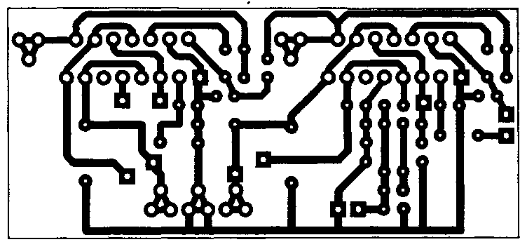
Figure: 2. Printed circuit board for the bridge version of the inclusion of TDA7294 microcircuits.

Figure: 3. Location of components for the bridge version of the inclusion of TDA7294 microcircuits.
To power such a power amplifier, a power supply with a transformer with a capacity of at least 250-300 watts is required. In the rectifier circuit, it is desirable to install electrolytic capacitors of 10000uF or more on each arm.
Bridging circuit from datasheet

Figure: 4. Bridge circuit for switching on two TDA7294 microcircuits (from the datasheet).
In the bridge mode of operation, the load resistance must be at least 8 ohms, otherwise the microcircuits will burn out from overcurrent!
Printed circuit board
Universal PCB for 2-channel and bridged power amplifier options.
The bridge switching circuit of the UMZCH is two identical channels, in one of which the signal input is connected to ground, and the feedback input (leg 2) is connected through a 22K resistor to the output of the second channel.
Also, the 10th legs of the microcircuits (Mute) and the 9th legs (Stand-By) must be connected to the mode control circuit, assembled on resistors and capacitors (Figure 6).

Figure: 5. Printed circuit board for the power amplifier on the TDA7294 microcircuits.
The boards have small deviations (for the better) from the schematic from the datasheet:
- At the inputs of the microcircuits (leg 3), capacitors are installed at 4 mkF, and not 0.56 mkF;
- A 470μF capacitor is connected between the 680 Ohm resistor (which goes to leg 2) and ground;
- Capacitors between pins 6 and 14 are 470μF, not 22μF;
- In terms of power supply, instead of 0.22mkF capacitors, it was proposed to install 680nF (0.68mkF);
In a bridged connection, pins 10 and 9 are tied together respectively and connected to the mode control circuit.

Figure: 6. Simple control scheme for Standby-Mute modes for TDA7294 microcircuits.
To turn on the microcircuits (remove from the quiet and energy-saving modes), the contacts "VM" and "VSTBY" just need to be connected to the positive power supply + Vs.
This printed circuit board is universal, it can be used for both two-channel and bridge modes of the amplifier on TDA7294 microcircuits. The ground wiring (GND) is very well done here, which will improve the reliability and noise immunity of the UMZCH.
Literature:
- Datasheet for TDA7294 chip - Download (7-Zip archive, 1.2MB).
- TDA7294 FAQ - cxem.net/sound/amps/amp129.php
Probably, any radio amateur is familiar with the microcircuit: a simple circuit, good sound quality, a low price. Recently I decided to take another look at the Lincor MF-1 Amplifier article again.
This is my first article and is intended for beginners who love good sound. Also presented is a drawing of the PCB and a manufacturing option for the amplifier case.
Getting to know me did not go very smoothly. At that time, there were a lot of fakes. They sometimes burned right at the first power supply, and if they started, they did not give out a sound, but something vaguely reminiscent of it, which is why I wanted to pour gasoline on the board and set fire to get rid of this ULF and never remember about it. Maybe my inexperience was also to blame, or maybe the topology of a 35 × 45 mm board of my own manufacture (when remembering that board, the author has goose bumps running through his body).
After reading it, it was decided to build according to the following criteria:
1) a clean power adapter without a volume control (the amplifier works in conjunction with a PC, from which the sound is also regulated),
2) 2 channels of double mono amplification (there were 2 transformers from UM Vega,
3) lower coeff. mutual penetration of channels and beautiful stereo),
4) forced cooling using 2 computer coolers and fans at low speeds,
5) and all this is obligatory in the case in the form of a finished structure, which is not a shame to put on Datagoras.

My version of PP
The case was, oddly enough, a homemade amplifier of my neighbor, a former radio amateur, assembled in the case of an unknown laboratory device. The reinforcement was placed on the landing, because was already unnecessary for him, and it is a pity to throw it in the trash. I remembered about this body when I decided to assemble the MF-1.
In the process of finalizing the case, simple and inexpensive parts were used:
Aluminum corner 15x15x1 mm, bought at HomeCenter.
M3 countersunk head bolts, nuts.
Metal spacers with M3 thread.
And here's what we got:

Transformers and filter

Rectifiers

End caps with coolers
It was the turn of the panels. Because we have cooling with a fan, the air must go somewhere and come from somewhere. First of all, I began to saw the back panel with an air outlet:

Everything was done with a drill, jigsaw, engraver and needle files. Now we cut out the lattice from the computer power supply case, clean the edges of the hole:


Now we take soldering acid, a soldering iron with a power of at least 100 W and solder the grating to the panel in several places:


We place the input and output connectors on the panel, MANDATORY ISOLATING THEM from the case:


We solder the shielding pin of the case to the panel. This will be the ONLY connection between the chassis and the power common wire. We connect the case with ground contacts of the input connectors through 1-2 W resistors with a nominal value of 1.5-2 Ohms. These measures are needed in order not to grab the "earth loop", which will spoil us in the form of a 50 Hz background.

Rear panel in place:

Now we transfer the Zobel circuit from the board to the output connectors of the PA. It doesn't quite fit on the board, because it (the chain) is a resonant system:

Now it's up to the front panel. Only the power switch is located on it. The panel itself is made of aluminum, behind it is a false panel made of moderately soft plastic, on which you can fix anything you want with M3 screws with countersunk heads. The button was used from an old dead cassette deck Wilma-104-Stereo:


The panel is fastened to the tin corners with hex bolts. That's it, the amplifier is ready!

Outcome
I wrote a comment about the sound in the topic about:Guys, I DIDN'T find out! I didn’t think I’ll ever say that, but it’s true! Nice soft bass, distinct highs (now I can distinguish between percussion and clapping on tracks that I know by heart), and all this pleasure on homemade 3-band PA with 8 "woofers.
I want to reassure everyone who is repulsed by the increased HF level: to the ear it is felt not as an increase in high frequencies, but as an increase in the quality of the source, an increase in "transparency".
And I still do not give up my words. For several months I did not get tired of the amplifier, as I often do. The sound is not annoying, you want to listen to everything and a lot, no matter at low or high volume.
By the way, about low volume. This ULF has a nice feature: at any volume level, the listener does not experience a lack of low frequencies, which can be compared with the use of TKRG, only with smooth (correct) control and without blocking the midrange.
In my version, the board is slightly redone. The choice of the "mute" and "standby" modes is thrown out as unnecessary, the main bank of capacitors is moved closer to the MC.
Power supply 2 × 23 V. The diodes KD213B are used in the rectifier. The electrolytes are shunted with a capacity of 100 nF, the secondary of the transformer - 47 nF.
Each MC is isolated from the radiators by a mica plate, while the radiators, in turn, are grounded to the case.
All wires are twisted together to reduce interference.
The background is not audible even with an open input, even close to the speaker. The goal, so to speak, has been achieved!
Further, the plans are to drill holes for air intake in the right side of the lower case cover, make a fan speed control device with temperature control of the radiators, it is possible to build in a preamplifier with a tone control, and paint the case.
We present to your attention a 100W class H stereo ULF, which is easy to assemble even for novice radio amateurs. TDA7294 integrated circuit in a monolithic Multiwatt15 case. It has a wide range of +/- 40V supply voltages and can provide high output power into 4 and 8 ohm loads.
There is built-in protection against short circuit in the load and protection against overheating (when reaching 145 degrees).
There is also a Mute function, which is used to eliminate clicks when turning on and stand-by mode. The range of reproducible frequencies is 20-20000Hz. Total harmonic distortion no more than 0.1%.
Please note that the microcircuit case is connected to -Vcc, so it should not be installed in a metal case without insulation. Otherwise, a short circuit to ground will occur. Do not forget to apply thermal paste before screwing the microcircuit to the heatsink.
Below is a schematic diagram of a power amplifier on the TDA7294 microcircuit.

The photo shows only one of the amplifier channels.

The figures show the printed circuit board and the location of the parts on it.


The photos show the assembly sequence of the boards
Notes:
The TDA7294 IC is not compatible with 1% tolerance resistors.
About 1000uF filter capacitors: If you are using speakers larger than 10 inches (25.4cm) in diameter, increase the capacitance to 2200uF.
Choosing a 47uF capacitor: I recommend using 47uF 50V from Elna SilmicII and 47uF 50V from Nichicon MUSE KZ.
The author of the article: P.E. Novik
Introduction
Amplifier design has always been a challenge. Fortunately, in recent years, there have been many integrated solutions that make life easier for amateur designers. I, too, did not complicate the task for myself and chose the simplest, high-quality, with a small amount of details, does not require tuning and stably operating amplifier on the TDA7294 chip from SGS-THOMSON MICROELECTRONICS. Recently, complaints about this microcircuit have spread on the Internet, which were expressed approximately as follows: "spontaneously excited, with incorrect wiring; burns, for any reason, etc.". Nothing like this. You can burn it only by incorrect switching on or closing, and cases of excitement have not been noticed even once, and not only with me. In addition, it has an internal load short-circuit protection and overheating protection. It also has a muting function (used to prevent clicks when turning on) and a standby function (when there is no signal). This IC is a class AB ULF. One of the main features of this microcircuit is the use of field-effect transistors in the preliminary and output amplification stages. Its advantages include high output power (up to 100 W at a load of 4 Ohm), the ability to operate in a wide range of supply voltages, high technical characteristics (low distortion, low noise level, wide operating frequency range, etc.), the minimum required external components and low cost
Main characteristics of TDA7294:
Parameter |
Conditions |
Minimum |
Typical | Maximum | Units |
| Supply voltage | ± 10 | ± 40 | IN | ||
| Frequency Response Range | signal 3db Output power 1W |
20-20000 | Hz | ||
| Long Term Power Output (RMS) | harmonic coefficient 0.5%: Uп \u003d ± 35 V, Rн \u003d 8 Ohm Uп \u003d ± 31 V, Rн \u003d 6 Ohm Uп \u003d ± 27 V, Rн \u003d 4 Ohm |
60 60 60 |
70 70 70 |
W | |
| Peak music output power (RMS), duration 1 sec. | harmonic coefficient 10%: Uп \u003d ± 38 V, Rн \u003d 8 Ohm Uп \u003d ± 33 V, Rн \u003d 6 Ohm Uп \u003d ± 29 V, Rн \u003d 4 Ohm |
100 100 100 |
W | ||
| Total harmonic distortion | Po \u003d 5W; 1kHz Po \u003d 0.1-50W; 20-20000Hz |
0,005 |
0,1 |
% | |
| Uп \u003d ± 27 V, Rн \u003d 4 Ohms: Po \u003d 5W; 1kHz Po \u003d 0.1-50W; 20-20000Hz |
0,01 |
% | |||
| Protection response temperature | 145 | 0 C | |||
| Quiescent current | 20 | 30 | 60 | mA | |
| Input impedance | 100 | kOhm | |||
| Voltage gain | 24 | 30 | 40 | dB | |
| Peak output current | 10 | A | |||
| Working temperature range | 0 | 70 | 0 C | ||
| Thermal resistance of the case | 1,5 | 0 C / W | |||
(PDF format).
There are a lot of switching circuits for this microcircuit, I will consider the simplest one:
Typical connection diagram:
List of elements:
| Position | Name | A type | number |
| C1 | 0.47 uF | K73-17 | 1 |
| C2, C4, C5, C10 | 22 μF x 50 V | K50-35 | 4 |
| C3 | 100 pF | 1 | |
| C6, C7 | 220 μF x 50 V | K50-35 | 2 |
| C8, C9 | 0.1 uF | K73-17 | 2 |
| DA1 | TDA7294 | 1 | |
| R1 | 680 Ohm | MLT-0.25 | 1 |
| R2 ... R4 | 22 k Ohm | MLT-0.25 | 3 |
| R5 | 10 kΩ | MLT-0.25 | 1 |
| R6 | 47 k Ohm | MLT-0.25 | 1 |
| R7 | 15 kΩ | MLT-0.25 | 1 |
The microcircuit must be installed on a radiator with an area\u003e 600 cm 2. Be careful, there is not a common, but a negative power supply on the microcircuit case! When installing the microcircuit on a radiator, it is better to use thermal grease. It is advisable to lay a dielectric (mica, for example) between the microcircuit and the radiator. The first time I did not attach any importance to this, I thought, why would I be so scared to close the radiator to the case, but in the process of debugging the structure, the tweezers that accidentally fell off the table closed the radiator to the case. The explosion was great! The microcircuits were simply blown to pieces! In general, I got off with a slight fright and $ 10 :). On a board with an amplifier, it is also advisable to supply powerful electrolytes of 10000mk x 50V to power, so that at power peaks, the wires from the power supply do not give voltage drops. In general, the larger the capacity of the capacitors on the power supply, the better, as they say, "you won't spoil the porridge with butter." Capacitor C3 can be removed (or not installed), that's what I did. As it turned out, it was because of him that when the volume control (a simple variable resistor) was turned on in front of the amplifier, an RC chain was obtained, which, with increasing volume, mowed high frequencies, but in general it is needed to prevent the excitation of the amplifier when ultrasound is applied to the input. Instead of C6, C7, I put 10000mk x 50v on the board, C8, C9, you can put any close value - these are power filters, they can be in the power supply, or you can solder them by hanging installation, which I did.
Pay:
I personally do not really like to use ready-made boards, for one simple reason - it is difficult to find exactly the same size elements. But in an amplifier, wiring can greatly affect sound quality, so it's up to you which board to choose. Since I was assembling an amplifier for 5-6 channels at once, the board, respectively, for 3 channels at once:

In vector format (Corel Draw 12)
Amplifier power supply, low-pass filter, etc.
Power Supply
For some reason, the amplifier's power supply raises many questions. In fact, it’s just there, everything is quite simple. The transformer, diode bridge and capacitors are the main elements of the power supply. This is enough to assemble the simplest power supply.

For powering a power amplifier, voltage stabilization is not important, and the capacitance of the capacitors is important, the more, the better. The thickness of the wires from the power supply to the amplifier is also important.
My power supply is implemented as follows:

+ -15V power supply is intended for power supply of operational amplifiers in the amplifier pre-stages. You can do without additional windings and diode bridges by feeding the stabilization module from 40V, but the stabilizer will have to extinguish a very large voltage drop, which will lead to significant heating of the stabilizer microcircuits. Stabilizer chips 7805/7905 are imported analogues of our KREN.
Variations of blocks A1 and A2 are possible:

Block A1 is a filter to suppress power noise.
Block A2 - block of stabilized voltages + -15V. The first alternative is simple to implement, for powering low-current sources, the second is a high-quality stabilizer, but requires an accurate selection of components (resistors), otherwise you will get a skew of the "+" and "-" arms, which will then give a skew of zero on the operational amplifiers.
Transformer
The power supply transformer for a 100W stereo amplifier should be about 200W. Since I was making a 5-channel amplifier, I needed a more powerful transformer. But I didn’t have to pump out all 100Watts, and all the channels cannot simultaneously take off the power. I came across a TESLA transformer (below in the photo) on the market for 250 watts - 4 windings with a wire of 1.5mm at 17V and 4 windings at 6.3V. By connecting them in series, I got the necessary voltages, although I had to rewind two 17V windings a little in order to get the total voltage of the two windings ~ 27-30V, since the windings were on top - it didn't take much work.
A great thing is a toroidal transformer, such are used to power halogen lamps in lamps, there are a lot of them in markets and shops. If structurally two such transformers are put one on top of the other, the radiation will be mutually compensated, which will reduce the pickup on the amplifier elements. The trouble is that they have one 12V winding. On our radio market you can make such a transformer to order, but this pleasure will be worth it. In principle, you can buy 2 transformers for 100-150 Watts and rewind the secondary windings, the number of turns of the secondary winding will need to be increased by about 2-2.4 times.
Diodes / diode bridges
You can buy imported diode assemblies with a current of 8-12A, this greatly simplifies the design. I used pulse diodes KD 213, and I did it separately on the bridge for each arm to give a current margin for the diodes. When turned on, powerful capacitors are charged, the current surge is very significant, at a voltage of 40 V and a capacity of 10,000 μF, the charging current of such a capacitor is ~ 10 A, respectively, along two arms of 20A. In this case, the transformer and rectifier diodes operate for a short time in short circuit mode. Breakdown of diodes by current will give unpleasant consequences. The diodes were installed on the radiators, but I did not detect the heating of the diodes themselves - the radiators were cold. To eliminate power supply interference, it is recommended to install a capacitor of ~ 0.33μF type K73-17 in parallel to each diode in the bridge. I really didn't. In the + -15V circuit, you can use bridges of the KTs405 type, for a current of 1-2A.
Design


Finished construction.
The most boring thing is the corps. As a case, I took an old slim case from a personal computer. I had to shorten it a little in depth, although it was not easy. I think that the case turned out to be successful - the power supply is in a separate compartment and you can put 3 more amplification channels into the case freely.

After field tests, it turned out that it is not out of place to put the fans to blow off the radiators, despite the fact that the radiators are quite impressive in size. I had to make a hole in the case from below and from above, for good ventilation. The fans are connected through a 100Ω 1W trimmer at the lowest speed (see next figure).
Amplifier block

The microcircuits are on mica and thermal paste, the screws must also be insulated. The heatsinks and the board are screwed to the case through dielectric posts.

Input circuits
I really wanted not to do this, only in the hope that this is all temporary ...

After hanging these guts, a small hum appeared in the speakers, apparently with the "ground" something was wrong. I dream of the day when I throw it all out of the amplifier and use it only as a power amplifier.
Adder board, low pass filter, phase shifter

Regulation block

Result
It turned out more beautiful from the back, even though you turn it forward with your booty ... :)

Construction cost.
| TDA 7294 | $25,00 |
| capacitors (powerful electrolytes) | $15,00 |
| capacitors (others) | $15,00 |
| connectors | $8,00 |
| power button | $1,00 |
| diodes | $0,50 |
| transformer | $10,50 |
| radiators with coolers | $40,00 |
| resistors | $3,00 |
| variable resistors + knobs | $10,00 |
| biscuit | $5,00 |
| body | $5,00 |
| operational amplifiers | $4,00 |
| surge Protectors | $2,00 |
| Total | $144,00 |
Yes, something was not cheap. Most likely, I did not take into account something, I just bought, as always, much more in total, because I had to experiment, and I burned 2 microcircuits and blew up one powerful electrolyte (I did not take all this into account). This is the calculation of a 5-channel amplifier. As you can see, the heatsinks turned out to be very expensive, I used inexpensive but massive CPU coolers, at that time (a year and a half ago) they were very good for cooling processors. Considering that an entry-level receiver can be bought for $ 240, then you can think about whether you need it :), though there is a lower quality amplifier. Amplifiers of this class cost about $ 500.
List of radioelements
| Designation | A type | Denomination | number | Note | Score | My notebook |
|---|---|---|---|---|---|---|
| DA1 | Audio amplifier | TDA7294 | 1 | Into notepad | ||
| C1 | Capacitor | 0.47 μF | 1 | K73-17 | Into notepad | |
| C2, C4, C5, C10 | 22 μF x 50 V | 4 | K50-35 | Into notepad | ||
| C3 | Capacitor | 100 pF | 1 | Into notepad | ||
| C6, C7 | Electrolytic capacitor | 220 μF x 50 V | 2 | K50-35 | Into notepad | |
| C8, C9 | Capacitor | 0.1 uF | 2 | K73-17 | Into notepad | |
| R1 | Resistor | 680 Ohm | 1 | MLT-0.25 | Into notepad | |
| R2-R4 | Resistor | 22 k Ohm | 3 | MLT-0.25 | Into notepad | |
| R5 | Resistor |


