Pulse power supply on ir2153 with protection. Simple UPS on IR2153 with overload and short circuit protection (300W)
This article published a diagram of the power supply unit on IR2153, which can be used as a power supply unit for the ULF. Also, this circuit can be used as a power source for a screwdriver by changing the output stage and recalculating the power transformer for the required voltage.
The actual circuit of the power supply unit on IR2153 with short-circuit protection is shown in the following screenshot.
Connector XT1 in the diagram - this is the connection of the self-supply winding of the microcircuit, which is wound on a power transformer and is designed for 15 volts. The circuit is started through a resistor R44 and a diode VD17. After starting the circuit, the microcircuit begins to write from this winding through the diodes VD2 and VD4.
The resistance of the resistor R44 is selected in such a way that the circuit starts reliably and during operation the resistor itself does not get very hot.
Connector XT2 the diagram shows the connection of the secondary windings of the current transformer.
A few words about protection against short-circuit. A current transformer is introduced into the circuit, the primary winding of which consists of one turn with a wire with a diameter of 1 mm. A transformer (ring) is placed on the board and through the window it is soldered to the board with a jumper, this jumper is the turn of the primary overlap.
Below, in the photo of the printed circuit board, the arrow indicates how the jumper is soldered.
The secondary winding of the current transformer contains two windings of 50 turns with a 0.2 mm wire.
With resistor R50, we select the desired current protection threshold. The D2 LED signals to us that the circuit is in protection mode.
I also wanted to note that the protection circuit works according to the "hiccuping" type, that is, if the output is short-circuited, then the protection turns off the microcircuit and there is no voltage at the output of the power supply, if the output is not short-circuited, then the power supply circuit with protection on ir2153 operates normally.
The screenshot shows the appearance of the printed circuit board from both sides. It also indicates the place where the jumper is soldered (white stripe), which is used as the primary winding of the current transformer (wrote about this above).

Photo of finished printed circuit boards of the power supply with protection on IR2153 made by hand.


Read the articles on the original site, do not support thieves.
External view of the switching power supply unit on IR2153
After making the printed circuit boards, it's time to start assembling this powerful power supply. The result of this work is shown in the following photos.


Files for making
To assemble this circuit of the power supply on ir2153 with protection, download the PCB file from this link.
The power supply is built on a floor bridge circuit based on the IR2153 microcircuit. At the output of this unit, you can get any voltage you need, it all depends on the parameters of the secondary winding of the transformer.
Consider in detail the circuit of a switching power supply.
The power supply with such components is about 150 watts.
The mains alternating voltage is supplied to the diode rectifier through a fuse and a thermistor.
After the rectifier, there is an electrolytic capacitor, which at the moment the unit is switched on to the network will be charged with a large current, the thermistor just limits this current. A capacitor is needed with a voltage of 400-450 volts. Further, constant voltage is supplied to the power switches. At the same time, power is supplied to the IR2153 microcircuit through a limiting resistor and a rectifier diode.
The resistor needs a powerful one, at least 2 watts, it is better to take a 5 watt one. The supply voltage for the microcircuit is additionally smoothed by a small electrolytic capacitor, with a capacity of 100 to 470 μF, preferably 35 Volts. The microcircuit begins to generate a sequence of rectangular pulses, the frequency of which depends on the rating of the timing circuit components, in my case the frequency is in the region of 45 kHz.
A midpoint rectifier is installed at the output. Rectifier in the form of a diode assembly in a TO-220 package. If the output voltage is planned within 40 volts, then you can use diode assemblies soldered from computer power supplies.
The voltage boost capacitor is designed for the correct operation of the upper field switch, the capacity depends on which transistor is used, but on average 1μF is enough for most cases.
Before starting, you need to check the operation of the generator. For these purposes, about 15 volts DC voltage is supplied from an external power source to the indicated microcircuit terminals.
Next, the presence of rectangular pulses on the gate of the field switches is checked; the pulses must be completely identical, of the same frequency and filling.
The first start-up of the power supply must be done through a 220 Volt safety lamp with a power of about 40 watts, be extremely careful not to touch the board during operation, after disconnecting the unit from the network, wait a few minutes until the high-voltage capacitor is discharged through the corresponding resistor.
It is very important to point out that this circuit does not have short circuit protection, therefore any short circuits, even short-term ones, will lead to the failure of the power switches and the IR2153 microcircuit, so be careful.
Collecting some next device, the question of how to power it is more and more tormented. Yes, it's good when in bulk of different equipment where there are suitable transformers, but if you rewind ??? Rewinding a transformer is not a pleasant occupation, even if the application for calculating the transformer helps in the calculations, the rewinding process itself is often annoying.
I remember how it was TSSH-180, a good anodic-incandescent trance, and I had to rewind. I was winding it up for two days, probably, plus spilled varnish so that the insulation was better and did not buzz ... I collected it, such a healthy one. He himself, weighing 3 kg, almost fell on his leg. I thought about it all and decided to switch to switching power supplies and there are a lot of reasons for this.
Reasons for choosing impulse power supplies:
1. P The first and not unimportant reason is financial. Here we have the same TSSH-180 a.-incandescent costs 150-180 UAH. While the SMPS 200W on the IR2153 assembly will cost 130-160 UAH. Yes, the difference is not great, but your home is full of the necessary parts. For example, I bought only IRF740 and IR2153 and paid 40 UAH. What's the difference ?? And I also got rid of the trash a little)) And it's also unforgettable that the bridge and the banks are already taken into account, and for the trance you also need to buy it. And good jars are well worth it. And on the SMPS instead of 22,000mF, you can put 3300mF and you won't even notice the difference in filtration
2.In The second reason is size. Transes are heavy, so 200 watts weighing 3-4kg, replaced by an SMPS weighing 300g and a board size somewhere 120 * 120mm. It is convenient to collect something powerful in a DVD box, for example Lanzar ...
3.E This is a low level of interference in the range of 20-20,000Hz. This is very good for a bass amplifier, even great. No interference, no background.
In the diagram we see the power part in which there is: protective circuits (R1, R2, FU1) CRC filter (C1, L1, C1), rectifier with a divider filter (VD1 (400V 3A), C3, C4, C6, C7, R44, R6) and a key part which includes two mosfets (VT1, VT2), a transformer (T1) and two noise suppressing circuits (R8C9, C8R7)
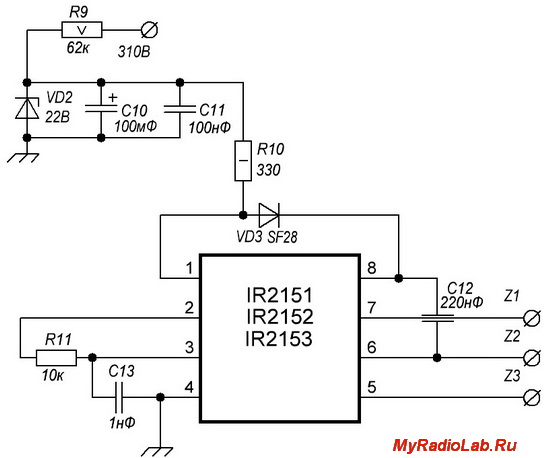
There is nothing complicated in the control part either. The supply part of the microcircuit consists of a ballast resistor R9, a Zener diode VD2. filter C10C11, and one more ballast resistor R10. In the course of work, you may have to pick up the R9R10.
The PWM frequency is set by R11C13. And it is calculated according to the formula f = 1 / 1.4 * (R11 + 75Ω) * C13. In our case, f = 1 / 1.4 * (10000 + 75) * 0.000000001 = 70896 Hz = 70.9 kHz comes out. Be careful with zeros

Well, there really is nothing to tell: Dual diode VD4, filter rectifier C14-L3-C15-C16 and that's it. Remember when calculating that this is not a stabilized PSU and the voltage can float. Therefore, it is better to enter a couple of volts less when calculating
The application for calculating Pulse Transformers will help you to calculate the transformer. Advice to wind the secondary with a scythe from a thinner wire in order to avoid skin-effect.
By the way, one of my acquaintances feeds from such a circuit 2.1 assembled on a TDA2030A with a total power of 65W. This is a small part of what the SMPS outputs on the IR2153, but it has been working for a year. Yes, again, a 70W transformer right now costs the same as the SMPS unit on IR2153, so there is also a 130W supply in the SMPS ...
That's all, thank you all for your attention and good luck with the assembly ...
The main component of the power supply under consideration is the IR2153 microcircuit (driver). This driver is available in two versions - IR2153 and IR2153D. The letter D means that the microcircuit is equipped with a diode designed to power the control stage of the upper switch. Thus, if the IR2153D driver is used in the circuit, then the diode D2 does not need to be installed. The generation frequency of this power source is set by the resistor R4 and the capacitor C6 connected to the pins of the RT (pin 2) and CT (pin 3) microcircuits. The optimal generation frequency of the microcircuit is a frequency of 40 - 70 kHz, it is for this range that the core of the Tr1 transformer is selected. A feature of the microcircuit is the ability to stop generation by shorting the CT output to minus. This principle is applied to organize the protection of the microcircuit against short circuits at the output of this power supply.
Electrical schematic diagram of a switching power supply unit on IR2153
How the power supply works
PULSE POWER SUPPLY WITH YOUR HANDS ON IR2153
Functionally, the IR2153 microcircuits differ only in the voltage boost diode installed in the planar case:

Functional diagram of IR2153

Functional diagram of IR2153D
First, let's look at how the microcircuit itself works, and only then we will decide which power supply to assemble from it. First, let's take a look at how the generator itself works. The figure below shows a fragment of a resistive divider, three op amps and an RS flip-flop:

At the initial moment of time, when the supply voltage was just applied, the capacitor C1 is not charged at all inverting inputs of the op-amp, there is zero, and on the non-inverting positive voltage formed by the resistive divider. As a result, it turns out that the voltage at the inverting inputs is less than at the non-inverting ones, and all three op amps at their outputs form a voltage close to the supply voltage, i.e. log unit.
Since the input R (zero setting) on the trigger is inverting, then for it it will be a state in which it does not affect the state of the trigger, but at the input S there will be a log of one, which also sets a log of one at the output of the trigger and a capacitor Ct through the resistor R1 will start charging. On the image the voltage across Ct is shown by the blue line,red - voltage at the output DA1, green - at output DA2, a pink - at the output of the RS trigger:

As soon as the voltage on Ct exceeds 5 V, a log zero is formed at the output of DA2, and when, while continuing to charge Ct, the voltage reaches a value slightly more than 10 volts, a log zero will appear at the output of DA1, which in turn will serve as the setting of the RS trigger to the state of log zero. From this moment, Ct will start discharging, also through the resistor R1, and as soon as the voltage across it becomes slightly less than the 10 V divider value, a log one will appear at the output of DA1. When the voltage across the capacitor Ct becomes less than 5 V, a log one appears at the output of DA2 and switches the RS flip-flop to the state of one and Ct will start charging again. Of course, at the inverse output of the RS flip-flop, the voltage will have opposite logical values.
Thus, at the outputs of the RS flip-flop, opposite in phase, but equal in duration, the levels of the log one and zero are formed:

Since the duration of the IR2153 control pulses depends on the charge-discharge rate of the capacitor Сt, it is necessary to carefully pay attention to flushing the board from the flux - there should be no leaks either from the terminals of the capacitor or from the printed conductors of the board, since this is fraught with magnetization of the power transformer core and failure power transistors.
There are also two more modules in the microcircuit - UV DETECT and LOGIK... The first of them is responsible for starting-stopping the generator process, depending on the supply voltage, and the second generates pulses DEAD TIME, which are necessary to eliminate the through current of the power stage.
Further, there is a separation of logical levels - one becomes the controlling upper arm of the half-bridge, and the second becomes the lower one. The difference lies in the fact that the upper arm is controlled by two field-effect transistors, which, in turn, control the output stage "torn off" from the ground and "torn off" from the supply voltage. If we consider the simplified circuit diagram for switching on the IR2153, then it turns out something like this:
Pins 8, 7 and 6 of the IR2153 microcircuit are, respectively, outputs VB, HO and VS, i.e. the power supply of the upper arm control, the output of the final stage of the upper arm control and the negative wire of the upper arm control module. Attention should be paid to the fact that at the moment of switching on, the control voltage is present at the Q RS of the flip-flop, therefore the power transistor of the lower arm is open. Capacitor C3 is charged through the diode VD1, since its lower output is connected to the common wire through the transistor VT2.
As soon as the RS trigger of the microcircuit changes its state, VT2 closes, and the control voltage at pin 7 of IR2153 opens the transistor VT1. At this moment, the voltage at pin 6 of the microcircuit begins to increase and to keep VT1 open, the voltage at its gate must be greater than at the source. Since the resistance of the open transistor is equal to tenths of Ohm, then the voltage at its drain is not much higher than at the source. It turns out that holding the transistor in the open state requires a voltage of at least 5 volts more than the supply voltage and it really is - the capacitor C3 is charged to 15 volts and it is he who allows VT1 to be kept open, since the energy stored in it in this the moment of time is the supply voltage for the upper arm of the microcircuit window stage. The VD1 diode at this moment in time does not allow C3 to be discharged to the power bus of the microcircuit itself.
As soon as the control pulse at pin 7 ends, the transistor VT1 closes and then VT2 opens, which again recharges the capacitor C3 to a voltage of 15 V.
Quite often, in parallel to the capacitor C3, amateurs install an electrolytic capacitor with a capacity of 10 to 100 μF, and without even delving into the need for this capacitor. The fact is that the microcircuit is capable of operating at frequencies from 10 Hz to 300 kHz and the need for this electrolyte is relevant only up to frequencies of 10 kHz, and then on condition that the electrolytic capacitor is of the WL or WZ series - they have technologically small ers and are more commonly known as computer capacitors with gold or silver ink inscriptions:

For popular conversion frequencies used in the creation of switching power supplies, frequencies are taken above 40 kHz, and sometimes they are brought to 60-80 kHz, so the relevance of using an electrolyte simply disappears - even 0.22 μF capacitance is already enough to open and hold the SPW47N60C3 transistor open , which has a gate capacitance of 6800 pF. To calm the conscience, a 1 μF capacitor is placed, and giving a correction for the fact that the IR2153 cannot switch such powerful transistors directly, the accumulated energy of the capacitor C3 is enough to control transistors with a gate capacity of up to 2000 pF, i.e. all transistors with a maximum current of about 10 A (the list of transistors is below, in the table). If you still have doubts, then instead of the recommended 1 μF, use a 4.7 μF ceramic capacitor, but this is pointless:

It would be wrong not to note that the IR2153 microcircuit has analogs, i.e. microcircuits with a similar functional purpose. These are IR2151 and IR2155. For clarity, we will summarize the main parameters in a table, and only then we will figure out which of them is better to cook:
CHIP |
Maximum driver voltage |
Start supply voltage |
Stop supply voltage |
Maximum current for charging power transistors gates / rise time |
Maximum current for discharging power transistor gates / fall time |
Internal Zener Voltage |
100 mA / 80 ... 120 nS |
210 mA / 40 ... 70 nS |
|||||
NOT SPECIFIED / 80 ... 150 nS |
NOT SPECIFIED / 45 ... 100 nS |
|||||
210 mA / 80 ... 120 nS |
420 mA / 40 ... 70 nS |
As you can see from the table, the differences between the microcircuits are not very large - all three have the same shunt zener diode in power supply, the start and stop supply voltages for all three are almost the same. The difference lies only in the maximum current of the final stage, which determines which power transistors and at which frequencies the microcircuit can control. Oddly enough, the most popular IR2153 turned out to be not a fish, not meat - it does not have a maximum current of the last stage of drivers, and the rise-fall time is somewhat prolonged. They also differ in cost - the IR2153 is the cheapest, but the IR2155 is the most expensive.
The generator frequency, it is the conversion frequency ( you don't need to divide by 2) for IR2151 and IR2155 is determined by the formulas below, and the frequency of IR2153 can be determined from the graph:

In order to find out which transistors can be controlled by the IR2151, IR2153 and IR2155 microcircuits, you should know the parameters of these transistors. The gate energy Qg is of the greatest interest when joining the microcircuit and power transistors, since it is this energy that will affect the instantaneous values of the maximum current of the microcircuit drivers, which means that a table with the parameters of the transistors is required. Here SPECIAL attention should be paid to the manufacturer, since this parameter differs from manufacturer to manufacturer. This is most clearly seen on the example of the IRFP450 transistor.
I perfectly understand that for a one-time production of a power supply unit of ten to twenty transistors, it is still a bit too much, nevertheless, I hung up a link for each type of transistor - I usually buy there. So click, see prices, compare with retail and the likelihood of buying a leftist. Of course, I'm not saying that Ali has only honest sellers and all the goods of the highest quality - there are a lot of crooks everywhere. However, if you order transistors that are produced directly in China, it is much more difficult to run into the dorm. And it is for this reason that I prefer STP and STW transistors, and I do not even hesitate to buy from disassembly, i.e. BOO.
POPULAR TRANSISTORS FOR PULSE POWER SUPPLIES |
|||||||
NAME |
VOLTAGE |
POWER |
CAPACITY |
Qg |
|||
MAINS (220 V) |
|||||||
17 ... 23nC ( ST) |
|
||||||
38 ... 50nC ( ST) |
|||||||
35 ... 40nC ( ST) |
|||||||
39 ... 50nC ( ST) |
|||||||
46nC ( ST) |
|||||||
50 ... 70nC ( ST) |
|||||||
75nC ( ST) |
|||||||
84nC ( ST) |
|||||||
65nC ( ST) |
|||||||
46nC ( ST) |
|
||||||
50 ... 70nC ( ST) |
|||||||
75nC ( ST) |
|||||||
65nC ( ST) |
|||||||
| STP20NM60FP | 54nC ( ST) |
||||||
|
|||||||
150nC (IR) |
|||||||
150 ... 200nC (IN) |
|||||||
252 ... 320nC (IN) |
|||||||
87 ... 117nC ( ST) |
|||||||


I g = Q g / t on = 63 x 10 -9 / 120 x 10 -9 = 0.525 (A) (1)
With the amplitude of the control voltage pulses at the gate Ug = 15 V, the sum of the driver output resistance and the limiting resistor resistance should not exceed:
R max = U g / I g = 15 / 0.525 = 29 (Ohm) (2)
Let's calculate the output impedance of the driver stage for the IR2155 microcircuit:
R on = U cc / I max = 15V / 210mA = 71.43 ohms
R off = U cc / I max = 15V / 420mA = 33.71 ohms
Taking into account the calculated value according to the formula (2) Rmax = 29 Ohm, we come to the conclusion that it is impossible to obtain the specified speed of the IRF840 transistor with the IR2155 driver. If a resistor Rg = 22 Ohm is installed in the gate circuit, the time to turn on the transistor is determined as follows:
RE on = R on + R gate, where RE - total resistance, R R gate - resistance installed in the gate circuit of the power transistor = 71.43 + 22 = 93.43 ohms;
I on = U g / RE on, where I on is the opening current, U g - gate control voltage = 15 / 93.43 = 160mA;
t on = Q g / I on = 63 x 10-9 / 0.16 = 392nS
The shutdown time can be calculated using the same formula:
RE off = R out + R gate, where RE - total resistance, R out - output impedance of the driver, R gate - resistance installed in the gate circuit of the power transistor = 36.71 + 22 = 57.71 ohms;
I off = U g / RE off, where I off - opening current, U g - gate control voltage = 15/58 = 259mA;
t off = Q g / I off = 63 x 10-9 / 0.26 = 242nS
To the resulting values, it is necessary to add the time of its own opening - closing of the transistor, as a result of which the real time t on will be 392 + 40 = 432nS, and t off 242 + 80 = 322nS.
Now it remains to make sure that one power transistor has time to close completely before the second starts to open. To do this, add t on and t off getting 432 + 322 = 754 nS, i.e. 0.754 µS. What is it for? The fact is that any of the microcircuits, be it IR2151, or IR2153, or IR2155, has a fixed value DEAD TIME, which is 1.2 µS and does not depend on the frequency of the master oscillator. The datasheet mentions that Deadtime (typ.) 1.2 µs, but there is also a very embarrassing figure from which the conclusion suggests itself that DEAD TIME is 10% of the duration of the control pulse:

To dispel doubts, the microcircuit was turned on and a two-channel oscilloscope was connected to it:

The power supply was 15 V, and the frequency turned out to be 96 kHz. As you can see from the photo, at 1 µS sweep, the pause duration is quite a bit more than one division, which exactly corresponds to about 1.2 µS. Then we decrease the frequency and see the following:

As you can see from the photo at a frequency of 47 kHz, the pause time practically did not change, hence the sign saying that Deadtime (typ.) 1.2 µs is true.
Since the microcircuits were already working, it was impossible to resist one more experiment - to lower the supply voltage to make sure that the generator frequency would increase. The result is the following picture:

However, expectations did not come true - instead of increasing the frequency, it decreased, and by less than 2%, which can be generally neglected and it should be noted that the IR2153 microcircuit keeps the frequency quite stable - the supply voltage has changed by more than 30%. It should also be noted that the pause time has slightly increased. This fact is somewhat pleasing - with a decrease in the control voltage, the opening time - closing the power transistors slightly increases and an increase in the pause in this case will be very useful.
It was also found out that UV DETECT copes with its function perfectly - with a further decrease in the supply voltage, the generator stopped, and with an increase, the microcircuit started again.
Now let's return to our math, according to the results of which we figured out that with 22 Ohm resistors installed in the gates, the closing and opening times for us are 0.754 µS for the IRF840 transistor, which is less than the 1.2 µS pause given by the microcircuit itself.
Thus, with the IR2155 microcircuit through 22 Ohm resistors, it is quite normal to be able to control the IRF840, but the IR2151 will most likely order to live a long time, since to close - open the transistors, we needed a current of 259 mA and 160 mA, respectively, and its maximum values are 210 mA and 100 ma. Of course, you can increase the resistances installed in the gates of the power transistors, but in this case there is a risk of going beyond DEAD TIME... In order not to engage in fortune-telling on the coffee grounds, a table was compiled in EXCEL, which you can take. It is assumed that the supply voltage of the microcircuit is 15 V.
To reduce switching noise and somewhat reduce the closing time of power transistors in pulse power supplies, either a power transistor is shunted by a series-connected resistor and a capacitor, or the power transformer itself is shunted with the same chain. This node is called a snubber. The resistor of the snubber circuit is selected with a nominal value of 5-10 times the drain-to-source resistance of the field-effect transistor in the open state. The capacitance of the capacitor of the circuit is determined from the expression:
C = tdt / 30 x R
where tdt is the pause time for switching the upper and lower transistors. Based on the fact that the duration of the transient process equal to 3RC should be 10 times less than the duration of the dead time value tdt.
Damping delays the moments of opening and closing of the field-effect transistor relative to the control voltage drops at its gate and reduces the rate of voltage change between the drain and the gate. As a result, the peak values of the impulses of the inflowing current are less, and their duration is longer. Almost without changing the turn-on time, the damping circuit significantly reduces the turn-off time of the field-effect transistor and limits the spectrum of radio interference generated.

With the theory sorted out a little, you can proceed with practical schemes.
The simplest circuit for a switching power supply on the IR2153 is an electronic transformer with a minimum of functions:
There are no additional functions in the circuit, and the secondary bipolar power supply is formed by two rectifiers with a midpoint and a pair of double Schottky diodes. The capacity of the capacitor C3 is determined at the rate of 1 μF of capacitance per 1 W of load. Capacitors C7 and C8 are of equal capacity and range from 1 μF to 2.2 μF. The power depends on the core used and the maximum current of the power transistors and theoretically can reach 1500 W. However, this is only THEORITICALLY
based on the fact that 155V AC voltage is applied to the transformer, and the maximum current of STP10NK60Z reaches 10A. In practice, all datasheets indicate a decrease in the maximum current depending on the temperature of the crystal of the transistor and for the STP10NK60Z transistor, the maximum current is 10 A at a crystal temperature of 25 degrees Celsius. At a crystal temperature of 100 degrees Celsius, the maximum current is already 5.7 A and we are talking about the temperature of the crystal, not the heat sink flange, and even more so about the temperature of the heatsink.
Therefore, the maximum power should be selected based on the maximum transistor current divided by 3 if it is a power supply for a power amplifier and divided by 4 if it is a power supply for a constant load, for example, incandescent lamps.
Considering the above, we find that for a power amplifier you can get a switching power supply with a power of 10/3 = 3.3A, 3.3A x 155V = 511W. For a constant load, we get a power supply unit 10/4 = 2.5 A, 2.5 A x 155V = 387W. In both cases, 100% efficiency is used, which does not happen in nature... In addition, if we proceed from the fact that 1 μF of the primary power supply capacity per 1 W of load power, then we need a capacitor, or capacitors with a capacity of 1500 μF, and such a capacity needs to be charged through the soft start systems.
A switching power supply with overcut protection and soft start on secondary power supply is shown in the following diagram:
First of all, this power supply unit has overload protection implemented on the current transformer. You can read more about the calculation of the current transformer. However, in the overwhelming majority of cases, a ferrite ring with a diameter of 12 ... 16 mm is quite enough, on which about 60 ... 80 turns are wound in two wires. Diameter 0.1 ... 0.15 mm. Then the beginning of one winding is connected from the ends of the second. This is the secondary winding. The primary winding contains one or two, sometimes one and a half turns is more convenient.
The resistor R4 and R6 are also reduced in the circuit in order to expand the range of the primary supply voltage (180 ... 240V). In order not to overload the Zener diode installed in the microcircuit, the circuit has a separate 1.3 W at 15 V.
In addition, a soft start for the secondary power supply was introduced into the power supply, which made it possible to increase the capacitance of the secondary power supply filters up to 1000 μF at an output voltage of ± 80 V. Without this system, the power supply was included in the protection at the moment of switching on. The principle of operation of the protection is based on the operation of the IR2153 at an increased frequency at the moment of switching on. This causes losses in the transformer and it is not able to deliver maximum power to the load. As soon as generation began through the divider R8-R9, the voltage supplied to the transformer goes to the VD5 and VD7 detector and the charging of the capacitor C7 begins. As soon as the voltage becomes sufficient to open VT1, C3 is connected to the frequency-setting circuit of the microcircuit and the microcircuit goes to the operating frequency.
Additional inductances for primary and secondary voltages are also introduced. The inductance for the primary power supply reduces the noise generated by the power supply and goes into the 220V network, and for the secondary power supply it reduces the HF ripple at the load.
In this variant, there are two additional secondary feeds. The first is intended for powering a 12-volt computer cooler, and the second is for powering the preliminary stages of the power amplifier.
Another subvariant of the circuit is a switching power supply with a unipolar output voltage:
Of course, the secondary winding is designed for the required voltage. The power supply can be soldered on the same board without mounting elements that are not on the diagram.
The next version of the switching power supply is capable of delivering about 1500 W to the load and contains soft start systems for both primary power supply and secondary power supply, has overload protection and voltage for a forced cooling cooler. The problem of controlling powerful power transistors is solved by using emitter followers for transistors VT1 and VT2, which discharge the capacitance of the gates of powerful transistors through themselves:
Such forcing the closing of power transistors allows the use of fairly powerful specimens, such as IRFPS37N50A, SPW35N60C3, not to mention IRFP360 and IRFP460.
At the moment of switching on, the voltage is supplied to the diode bridge of the primary power supply through the resistor R1, since the contacts of the relay K1 are open. Further, the voltage through R5 is supplied to the microcircuit and through R11 and R12 to the output of the relay winding. However, the voltage increases gradually - C10 is of a sufficiently large capacity. From the second winding of the relay, the voltage is supplied to the Zener diode and the thyristor VS2. As soon as the voltage reaches 13 V, it will already be enough to open VS2 after passing the 12-volt zener diode. It should be recalled here that IR2155 starts at a supply voltage of about 9 V, therefore, at the time of opening VS2 through IR2155 will already generate control pulses, only they will enter the primary winding through resistor R17 and capacitor C14, since the second group of contacts of relay K1 is also open ... This will significantly limit the charging current of the secondary power filter capacitors. As soon as the thyristor VS2 opens, voltage will be applied to the relay coil and both contact groups will close. The first will bypass the current-limiting resistor R1, and the second - R17 and C14.
On the power transformer it has a service winding and a rectifier on diodes VD10 and VD11 from which the relay will be powered, as well as additional feeding of the microcircuit. R14 serves to limit the forced cooling fan current.
Used thyristors VS1 and VS2 - MCR100-8 or similar in TO-92 package
Well, at the end of this page, one more circuit is all on the same IR2155, but this time it will act as a voltage regulator:
As in the previous version, the power transistors are closed by bipolar VT4 and VT5. The circuit is equipped with a soft start of the secondary voltage at VT1. The start is made from the on-board network of the car and then the power is supplied with a stabilized voltage of 15 V, which is formed by diodes VD8, VD9, a resistor R10 and a Zener diode VD6.
There is another rather curious element in this circuit - tC. This is a heat sink overheating protection that can be used with almost any inverter. It was not possible to find an unambiguous name, in the common people it is a self-restoring thermal fuse, in the price lists it usually has the designation KSD301. It is used in many household electrical appliances as a protective or temperature regulating element, since they are available with different response temperatures. This fuse looks like this:

As soon as the heatsink temperature reaches the cut-off limit of the fuse, the control voltage from the REM point will be removed and the inverter will turn off. After the temperature has dropped by 5-10 degrees, the fuse will restore and supply the control voltage and the converter will start again. The same thermal fuse, or a thermal relay, can also be used in network power supplies by controlling the temperature of the radiator and turning off the power, preferably low-voltage, going to the microcircuit - the thermal relay will work this way longer. You can buy the KSD301.
VD4, VD5 - fast diodes from the SF16, HER106 series, etc.
Overload protection can be introduced into the circuit, but during its development, the main emphasis was on miniaturization - even the soft start node was a big question.
The manufacture of coil parts and printed circuit boards is described on the following pages of the article.
Well, at the end of the day, there are several schemes of switching power supplies found on the Internet.
Scheme No. 6 is taken from the "SOLDERING" website:
In the next power supply unit on the self-clocked IR2153 driver, the capacity of the boost capacitor is reduced to a minimum sufficiency of 0.22 μF (C10). The microcircuit is powered from the artificial midpoint of the power transformer, which is not essential. There is no overload protection, the shape of the voltage supplied to the power transformer is slightly corrected by the inductance L1:
Choosing schemes for this article, I came across this one. The idea is to use two IR2153s in a bridge converter. The author's idea is quite clear - the output of the RS flip-flop is fed to the input Ct and, according to logic, control pulses of the opposite phase should be formed at the outputs of the slave microcircuit.
The idea intrigued and was continued an investigative experiment on the topic of performance testing. It was not possible to get stable control pulses at the outputs of IC2 - either the upper driver worked, or the lower one. In addition, the pause phase shifted DEAD TIME, on one microcircuit relative to another, which will significantly reduce the efficiency and the idea was forced to abandon.

A distinctive feature of the next power supply unit on IR2153 is that if it works, then this work is akin to a powder keg. First of all, I was struck by the additional winding on the power transformer to power the IR2153 itself. However, after diodes D3 and D6, there is no current-limiting resistor, which means that the fifteen-volt zener diode inside the microcircuit will be VERY heavily loaded. What happens when it overheats and thermal breakdown is anyone's guess.
Overload protection on VT3 bypasses the time of the driving capacitor C13, which is quite acceptable.
The last acceptable version of the power supply circuit on the IR2153 is nothing unique. True, the author for some reason too much reduced the resistance of the resistors in the gates of the power transistors and installed zener diodes D2 and D3, the purpose of which is not quite clear. In addition, the capacitance C11 is too small, although it is possible we are talking about a resonant converter.
There is another version of a switching power supply using the IR2155, and it is to control a bridge converter. But there the microcircuit controls the power transistors through an additional driver and a matching transformer, and we are talking about induction melting of metals, so this option deserves a separate page, and everyone who understands at least half of what he read should go to the page with PCBs.
SELF-ASSEMBLY VIDEO INSTRUCTIONS
PULSE POWER SUPPLY BASED ON IR2153 OR IR2155
A few words about the manufacture of pulse transformers:
How to determine the number of turns without knowing the ferrite grade: