Gas Discharge Clock - PCB Etching. Gas discharge lamp clock V2.0 Gas discharge lamp clock in 14
I greet users again and keep my promise!
Today I'm starting to upload a detailed photo report on the manufacture of watches on gas-discharge indicators (GDI). The IN-14 was taken as a basis.
All manipulations in this and the following posts are available for a person without experience, just have a little skill. I will divide the work into several parts, each of which will be described in detail by me and posted on the network.
We proceed to the first stage - etching the boards. After researching the literature, I found several technologies:
- ... Three components are needed to work: a laser printer, ferric chloride and an iron. The method is the simplest and cheapest. He has only one drawback - it is difficult to transfer very thin tracks.
- Photo-resist. To work, you need the following materials: photo-razist, film for a printer, soda ash and a UV lamp. The method allows you to etch circuit boards at home. The downside is that its cost is not cheap.
- Reactive ion etching (RIT)... For work, a chemically active plasma is needed, so it is not feasible at home.
Anodic etching is most often used. The process of anodic etching consists in the electrolytic dissolution of the metal and the mechanical separation of oxides by the evolved oxygen.
It is quite understandable that I chose the LUT method for etching boards. The list of required equipment and materials should look something like this:
- Ferric chloride. He is bathed in radio goods at a price of 100-150 rubles per can.
- Foil glass tectolite. You can find it in radio stores, radio flea markets, or factories.
- Capacity. A regular food container will do.
- Iron.
- Glossy paper. Self-adhesive paper or a plain glossy magazine page will do.
- Laser printer.
IMPORTANT! The print version should be mirrored, since when the image is transferred from paper to copper, it will be displayed back.
You need to make a markup and cut off a piece of PCB for the board. This is done with a hacksaw for metal, a breadboard knife or, in my case, a drill.
After that, I cut out a sketch of the future board from paper and attached it to the textolite (on the foil side) with a drawing. The paper is taken with a margin in order to wrap the textolite. We fix the sheet from the back side with adhesive tape for fixing.
From the side of the picture, we draw it over the future board with an iron several times through A4 sheet. It will take at least 2 minutes of vigorous ironing to convert the toner to copper.
We substitute the workpiece under a stream of cold water and easily remove the paper layer (the wet paper should move freely by itself). If the surface has not been heated sufficiently, small pieces of toner may come off. We finish them with cheap nail polish. As a result, the blank for the board should look like this:
In the prepared container, prepare a solution of ferric chloride and water. It is better to use hot water for these purposes, this will increase the reaction rate. It is better to refuse boiling water, since the high temperature deforms the board. The finished liquid should be the color of a medium-brewed tea. We place the board in the solution and wait for the excess foil to completely dissolve.
If you occasionally stir the solution in the container, then the reaction rate will also increase. Ferric chloride is not harmful to the skin of the hands, but fingers can become stained.
To make the process more clear, I placed the board partially in the solution. What changes should occur can be seen in the photo:
Excess copper dissolves in the composition after about 40 minutes. After that, the etching process can be considered complete. It remains only to make a few holes. We mark with an awl and drill small holes with a drill. The tool must be run at high revs so that the drill does not slide out. The result should look something like this:
The second stage in the manufacture of watches on the GRI is the soldering of the components. I will talk about this in my next post.
Downloading:
- Program ).
- Post about component soldering -;
- Post about microcontroller firmware -;
- Post about the manufacture of the case -.
Convenient fringe cutter for transformers. Soldering iron heating regulator with power indicator
Kind time of the day to all respected Muskovites. I want to tell you about an interesting radio designer for those who know from which end the soldering iron heats up. In short: the set brought positive emotions to those interested in this topic - I recommend it.
Details below (careful, a lot of photos).
I'll start from afar.
I myself do not consider myself to be a true radio amateurs. But I am not alien to a soldering iron and sometimes I want to design / solder something, well, I try to do minor repairs of the electronics around me on my own (without causing irreparable harm to the experimental device), and in case of failure I turn to professionals.
Once, under the influence, I bought and assembled the same watch. The design itself is simple there and the assembly did not present any difficulties. I put the clock in my son's room and calmed down for a while.
Then, after reading, I wanted to try to assemble them too, at the same time practicing soldering smd components. In principle, here everything worked right away, only the sound signal buzzer was silent, I bought it offline, replaced it and that's it. Gave the watch to a friend.
But I wanted something else, more interesting and more complicated.
Once, while poking around in my father's garage, I came across the remains of some kind of electronic device of the Soviet era. Actually, the remains are a kind of circuit board structure that contained 9 IN-14 gas-discharge indicator lamps.
Then the thought came to me - to collect a watch on these indicators. Moreover, I have been observing such a clock, once collected by my father, in my parents' apartment for 30 years, if not more. I carefully unsoldered the board and became the owner of 9 lamps from the beginning of 1974. The desire to incorporate these rarities into the business has intensified.
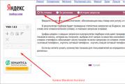
Through meticulous questions from Yandex, I went to the site, which turned out to be just a storehouse of wisdom on the creation of such a watch. After looking through several diagrams of such structures, I realized that I wanted a clock controlled by a microcontroller, with a real-time microcircuit (RTC). And if, repeating one of the clock designs, I would have been able to program the controller and solder the board, then the issue of making the printed circuit board itself puzzled me (I'm not a true radio amateur yet).
In general, it was decided to start with buying a designer of such watches.
this constructor is being discussed, in fact, this is the author's topic (his nickname mss_ja) of this set, where he himself helps with the assembly and launch of his sets. He also has a lot of photos of finished products. There you can buy not only kits for self-assembly, but also ready-made watches. Look, penetrate.
Some doubts were raised by the issue of delivery, because the respected author lives in Ukraine. But it turned out that the war is a war, and the post office works on schedule. Actually 14 days and I have the package.
delivery

Here is such a box.

So what did I buy? And everything can be seen in the photo.

The set includes:
a printed circuit board (on which the author has kindly unsoldered the controller, so that I do not suffer, his legs are too small). The program has already been wired into the controller;
Package with construction components. Large ones are clearly visible - microcircuits, electrolytic capacitors, tweeter, etc., according to the diagram and description. Under this bag is another one, with small smd components - resistors, capacitors, transistors. All smd elements are glued on paper with inscribed denominations, very convenient. Photo taken during assembly.

The blank for the watch case is not included in the set by default, but after writing off with the author, I bought it. This is a reassurance against your possible curvature, tk. I practically have no business with a tree, and all the experience of processing it comes down to periodic sawing of firewood for a shish kebab in the country. And I wanted a classic look - like "glass from a piece of wood", as they say on the radio cat forum.
So let's get started.
That's all we need to start building. And to complete it successfully, we still need a head and hands.

But no, he didn’t show everything. You don't even have to start without this thing. These smd elements are so small ...

The assembly began strictly on the recommendation of the author - with power converters. And there are two of them in this design. 12V-> 3.3V for electronics power supply and 12V-> 180V for the indicators themselves. It is necessary to collect such things very carefully, after making sure that you are soldering exactly that, exactly there and without confusing the polarity of the components. The printed circuit board itself is of excellent quality, industrial production, it is a pleasure to solder.
The power converters were assembled and tested for the correct voltages, then began to install the remaining components.
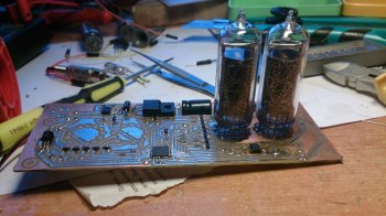
Starting the assembly process, I made a promise to myself to photograph every stage of it. But, carried away by this action, I remembered my desire to write a review only when the board was almost ready. Therefore, the next photo was taken when I started testing the indicators by simply plugging them into the board and applying power. 
Of the nine IN-14 lamps I obtained, one turned out to be completely inoperative, but the rest were in excellent condition, all the numbers and commas glowed perfectly. 6 lamps went to hours, and two to the reserve. 
I deliberately did not wash the manufacturing date from the lamps.
back side 

Here you can see a clumsily installed photoresistor, I was looking for its best position.
So, after making sure that the circuit worked and the clock was running, I put it aside. And he took up the corps. The lower part is made of a piece of fiberglass from which I ripped off the foil. And the piece of wood was carefully sanded with fine sandpaper to a state of "pleasant smoothness." Well, then it is covered with varnish with a stain in several layers with intermediate drying and polishing with fine sandpaper. 
It turned out not perfect, but, in my opinion, good. Especially considering my lack of experience with wood. 
At the back you can see holes for connecting the power supply and a temperature sensor, which I do not have yet (yes, it can also show the temperature ...). 
Here are a few shots in the interior. It is impossible to sensibly photograph in any way, the photos do not convey all the "trick". 
This is a date display. 
Illumination of lamps. Well, where is the same without her. It is switchable, if you do not like it, do not turn it on.
Remarkable precision. For a week I have been watching the clock, a second goes by a second. Of course, a week is not a period, but the trend is obvious.
In conclusion, I will give the characteristics of the clock, which I copied and pasted directly from the site of the author of the project:
Watch features:
Clock, format: 12/24
Date, format: HH.MM.YY / HH.MM.D
Alarm clock customizable by day.
Temperature measurement.
Hourly signal (switchable).
Automatic brightness control based on lighting.
High precision (DS3231).
Indication effects.
--- no effects.
--- smooth fading out.
--- scrolling.
--- overlay numbers.
Separation lamp effects.
--- disabled.
--- blinking 1 hertz.
--- smooth fading out.
--- blinking 2 hertz.
--- included.
Date display effects.
--- no effects.
---Shift.
--- Scroll shift.
--- Scrolling.
--- Digit replacement.
Pendulum effect.
---simple.
---difficult.
Backlights
--- Blue
--- Ability to illuminate the case. (Optional)
So, let me summarize. I really liked the watch. Assembling a watch from a set is not difficult for a person of average curvature. After spending a few days on a very interesting activity, we get a beautiful and useful device, even with a touch of exclusivity.
Of course, by today's standards, the price is not very humane. But firstly, this is a hobby, it is not a pity to spend money on it. And secondly, the author is not to blame for the fact that the ruble is now worthless.
Lamp : IN-14
Scheme: there is
Pay: No
Firmware: there is
Source: No
Description: there is
Peculiarities: authoring from Myxomop.
Scheme:
A clock of our own design. There is an alarm clock and a service menu where you can change the clock settings. You can turn on the "fight" - when the hour changes, the clock beeps the number of hours.


The power supply is the simplest impulse one. I did it according to this scheme

You can see my joint on the board near the crystal oscillator. I'm used to controllers, like everything can be changed programmatically. And here the outputs of the decoder (hard logic) rule with the keys, when developing the circuit I did not even think about it, I need to supply 1 or 0. I connected the outputs of the decoder with the keys purely automatically. Then I was looking for an error in the program for a long time. When it finally dawned on me what was the matter, I swore for half a day.


When all the jambs (both hardware and software) were fixed, we got such a watch.

I will give a short list of the functions of the service menu:
1
- on (1) / off (0) battle
2
- on (1) / off (0) show insignificant "0" in the most significant digit of the clock
3
- 12/24 hour cycle of time display (if a 12-hour cycle is selected, when setting the time, the clock automatically switches to a 24-hour cycle, and then returns back)
4
- 4 variants of dividing point blinking
5
- 4 sound options for the alarm (you can listen to the sound with the "Set" button)
6
- the number of cycles of playing the alarm sound (1-99)
7
- correction number for timing
8
- on (1) / off (0) smooth change of numbers
9
- writing the settings to the eeprom (occurs once each time you enter this menu item, while the blinking "0" is set to "1")
The service menu can be entered by pressing the "Set" and "Mode" buttons simultaneously. The "Set" button must be pressed first. The output is the same.
If the clock does not run accurately enough, you can try to change the correction number in the service menu. You can calculate it like this. First, we write there 0. And leave it for exactly one day. During this time, the clock must necessarily run forward. If they are behind, then no correction will help, most likely the reason is in quartz - just change! So, we look at how many seconds they went ahead ( sek) we calculate this number approximately by the formula korr = 43.2 / sek... Then you can detect it again in a few days and try to change it to +/- 1 and see if there will be any improvements.
Well, if you decide to repeat my design, I post the firmware.
Firmware .
The only crap that we could not overcome is the ringing (squeak) of indicators from the dynamic indication. Judging by the experience of other nixist builders, there is nothing to be done about it, such is the design of the lamps themselves.
DIY clock on IN-14 lamps
I have long wanted to post an article on manufacturing do-it-yourself clock on IN-14 lamps, or how else, steam-punk-style watches respond.
I will try to outline only the most important things in stages and dwelling on the key points. The clock indication is clearly visible both day and night, and by themselves they look very nice, especially in a good wooden case.
Diagram of the device (to enlarge-like everywhere-click):
This watch is equipped with IN-14 gas-discharge indicators. They can also be replaced with IN-8, of course, taking into account the differences in pinout. The numbering of the indicator pins is carried out clockwise from the side of the pins. For IN-14, pin 1 is indicated by an arrow.


Watch characteristic:
| Supply voltage, V | 12 |
| Consumption current, no more, mA | 200 |
| Typical current consumption, mA | 150 |
| Indicators type | IN-14 |
| Time display format | Hours \ Minutes \ Seconds |
| Date display format | Day month Year |
| Number of control buttons | 2 |
| Alarm clocks | 2 |
| Discreteness of setting the alarm clock operation time, min | 5 |
| Program gradations for adjusting the brightness of the indicators | 5 |

Atmega8 microcontroller in TQFP package. The operation of the clock with a controller in a DIP package is not provided. Real time clock DS1307. The sound emitter has a built-in generator and a 5V supply voltage. All necessary project files - board, controller firmware - download
Fuses:

One more photo:

The step-up voltage converter is made on the MC34063A microcircuit. (MC33063A). In terms of prevalence and cost, it is somewhat inferior to the 555 timer, on which such a converter can be built, however, it is cheaper and more affordable than the MAX1771.
Non-polar capacitors are ceramics, polar ones are Low ESR electrolytes. If Low ESR is not available, place ceramic or film parallel to the electrolyte. The choke in the step-up converter is 220 μH for a current of 1.2A. The minimum rated inductor value is 180 μH, and the minimum rated inductor current is 800 mA.

The decoders are operated by two K155ID1 buildings. The anode voltage switch uses the TLP627 optocoupler. The values of R23 and R24 must be selected independently, depending on the degree of luminescence. Without them, the currents through the points exceed the permissible level. During installation, we do not push the indicators completely. Since the housings of all indicators are individual, they will need to be aligned with the printed circuit board and with each other.
Clock control on IN-14:
The transition from one mode to another is carried out along the ring with the button "MODE".
The value is set by the button "SET".
The value to be corrected is either blinking or brighter.
Setting the seconds value is to zero them.
Setting the value of minutes, hours, day, month, year consists in adding 1 to the current value along the ring to the maximum value, after which the value is reset to zero.
The setting of the minutes for the alarm clock is made from zero with a discreteness of 5 minutes (00-05-10-15: 55).
If the watch is not in the main mode and pressing the buttons stops, then after a few minutes the watch returns to the main mode.
Cancellation of the sound signal of the alarm clock is made by the button "SET".
In this case, the next time the alarm time is reached, the alarm will be activated. The commas in tens and units of seconds indicate that alarm clocks 1 and 2 are active, respectively. The clock operating modes are shown in the table. Red conventionally denotes brightly burning discharges, orange - dimly illuminated discharges, black - extinguished discharges. For time: H - hours, M - minutes, S - seconds. For a date: D - day of the month (day), M - month, Y - year. To set an alarm: 1 - alarm 1, 2 - alarm 2, X - no value (extinguished).
First start-up, controller programming and setup. Check first the correct installation of the clock circuit. Then check the power circuits for a short circuit. If not found, try feeding the input from a 12V source. If there is no smoke, check the voltage of the D5V0 supply circuit. Using the trimmer resistor RP1, set the output of the boost converter to 200V (for the specified ratings). Wait a few minutes. The elements of the circuit should not noticeably heat up. This is especially true for the choke of the high-voltage converter. Its overheating indicates an incorrectly selected rating or a design with too low operating current. Such a choke must be replaced with a more suitable one.

From this point on, you will need a VT1 type CR2032 battery. In extreme cases, short-circuit the contacts of the battery panel, but then the time and date will be set every time the power supply is cut off.

Program sequentially Flash and EEPROM microcontroller using the supplied firmware. This operation must be done in the specified sequence. The indicators will display " 21-15-00 ". The seconds will" go. "If you still haven't connected BT1, then instead of time and date you will see something like 05-05-05 ".
Set the values of time, date, alarms in accordance with the table describing the operating modes. When you get to the brightness setting, programmatically turn on the minimum brightness of the indicators. Adjust the boost converter so that each indicator is lit at minimum brightness, but completely. That is, it should not be so that part of the indicator's digit is lit, and part is not. Then programmatically set the maximum brightness and check the glow of the indicator digits.
Indicators should not glow too brightly, and there should be no "volumetric" glow. Brightness correction is again done with RP1. After that, check the glow again at minimum brightness, and so on until you get acceptable results. If acceptable results are not obtained, try to select the values of the anode resistors and repeat the above steps.
Such watches will compare favorably with ordinary Chinese ones, on LEDs, which, by the way, cost a lot of money.
Video of work in our group VK-
Recently, watches in the spirit of retro, on gas-discharge indicators, have been very popular. In foreign countries such a clock is called "Nixie-clock". Seeing a similar project on the Internet, I got the idea to collect the same ones for myself.
Read on to see what came out of this.
I studied the options for schemes on the Internet. Typically, a Nixie watch has four main parts:
1.controller microcontroller,
2.high-voltage power supply,
3. driver-decoder and the actual lamp.
In most circuits, Soviet K155ID1 microcircuits - "high-voltage decoders for controlling gas-discharge indicators" are used as a decoder. I couldn't find such a chip, and I didn't really want to use DIP-packages.
Clock scheme, applied details
Taking into account the available components, I developed my own version of the clock circuit, in which the role of the decoder is assigned to the microcontroller.
Figure 1. Schematic of Nixie-clock on MK
On the U4 MC34063 microcircuit, a step-up "dc-dc" converter with an external switch on the IRF630M is assembled in a fully insulated case. The transistor is taken from the monitor board.
R4 + Q1 + D1 is a simple driver for the key, discharging the shutter quickly. Without such a driver, the key was very hot and it was not possible to obtain the required voltage.
R5 + R7 + C8 - feedback that determines the output voltage at 166 volts. Transistors Q3-Q10 together with resistors R8-R23 constitute anode switches, allowing for dynamic indication.
Resistors R8-R11 set the brightness of the indicator digits, and resistor R35 - the brightness of the dividing point.
The terminals of the same name of all lamps, with the exception of the anode, are interconnected and controlled by transistors Q11-Q21.
The ATMEGA8 microcontroller controls the lamp keys, it also polls the DS1307 real-time clock (RTC) chip and buttons.
Diodes D3 and D4 provide the generation of an external interrupt request by pressing any of the control buttons.
The controller is powered via a 78L05 linear regulator.
IN-14 lamps are glow discharge indicators.
Cathodes in the form of Arabic numerals, 18 mm high and two commas. Indication is carried out through the lateral surface of the cylinder. The design is glass, with flexible leads.

So to speak, uh ... the Iskra 122 calculator. Photo ~ MERCURY LIGHT ~
The IN-14 indicators from the monstrous Iskra 122 calculator produced in 1978 shine without any problems and I got it for “thank you for clearing my balcony”.
The structure can be powered with a constant voltage of 6 - 15 Volts from an external power supply unit. Consumption less than one Watt (70 mA @ 10 V).
To keep the clock running in the event of a power failure, a CR2032 battery is provided. According to the datasheet, the DS1307 only consumes 500nA on battery power, so this battery will last for a very long time.
Watch management
After power is applied, four zeros will light up, and if communication with the DS1307 microcircuit is established without errors, the dividing point will start blinking.The time is set using the three buttons "+", "-" and "set". Pressing the "set" button will extinguish the hour digits, then, using the "+" and "-" buttons, the minutes are set. The next press on the "set" button will switch to the clock setting mode. Another press on "set" will reset to 0 seconds and switch the clock to the time display mode "HH: MM". The dividing point will flash.
By holding the "+" button, you can at any time view the current time in the "MM: SS" mode.
Pay
All the main parts of the circuit are laid out on one double-sided board measuring 135 × 53 mm. The board was made with LUT and etched in hydrogen peroxide with citric acid. The layers of the board were connected to each other by soldering pieces of copper wire into the holes.I matched the templates of the board through the marks outside the board. It is worth recalling that the top layer M1 in Sprint-Layout must be printed mirror-like.
During the test assembly, "jambs" were identified in the layout. I had to connect the anode transistors with wires. The printed circuit board in the archive for the article has been fixed.
Contact pads are provided for programming the controller.
Photo of the assembled clock board
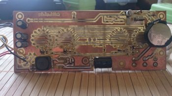
Photo 1. Clock board below

High voltage el. the capacitor is placed horizontally, for it I made a cut in the PCB. I tried to make the assembled board as small as possible. It turned out to be only 15 mm thick. You can make a slim stylish case!

Parts List

Files
The archive contains a clock circuit in high resolution, a printed circuit board in SL5 format and a firmware for the controller.Fuses must be configured to operate from an internal 8 MHz oscillator.
▼ 🕗 24/05/15 ⚖️ 819.72 Kb ⇣ 137 Hello reader! My name is Igor, I'm 45, I'm a Siberian and an avid amateur electronics engineer. I have invented, created and maintain this wonderful site since 2006.
For more than 10 years, our magazine has existed solely on my funds.
Good! The freebie is over. If you want files and useful articles - help me!