How to write your operating system. How to create your own operating system from scratch
This series of articles is devoted to low-level programming, that is, a computer architecture, a device of operating systems, programming in the assembler language and adjacent regions. So far, two Habrazer - Iley and Pehat are engaged in writing. For many high school students, students, and professional programmers, these topics turn out to be very difficult in teaching. There are many literature and courses dedicated to low-level programming, but it is difficult for them to make a complete and inclusive picture. It is difficult to read one or two books on assembler and operating systems, at least in general terms to imagine how this complex system of iron, silicon and a variety of programs is actually working - a computer.
Everyone solves the learning problem in its own way. Someone reads a lot of literature, someone tries to quickly go to practice and understand the way, someone is trying to explain to friends everything he himself. And we decided to combine these approaches. So, in this course of articles, we will demonstrate step by step, as the simple operating system is written. Articles will be considered a review, that is, they will not be exhaustive theoretical information, but we will always try to provide links to good theoretical materials and answer all the questions that arise. We have no clear plan, so many important decisions will be taken along the way, taking into account your feedback.
Perhaps we will deliberately make the development process in a dead end to allow you to fully realize all the consequences of an incorrectly accepted solution, as well as hone on it some technical skills. So you should not perceive our solutions as the only true and blindly believe us. We emphasize once again that we expect from readers of activity in discussing articles, which should greatly affect the overall process of developing and writing follow-up articles. Ideally, I would like with time some of the readers joined the development of the system.
We will assume that the reader is already familiar with the basics of assembler and si languages, as well as the elementary concepts of computer architecture. That is, we will not explain what register is or, say, RAM. If you won't have enough knowledge, you can always refer to additional literature. A brief list of references and links to sites with good articles is at the end of the article. It is also desirable to be able to use Linux, since all compilation instructions will be given exactly for this system.
And now - closer to business. In the remainder of the article, we write a classic program "Hello World". Our Helloovo will succeed a bit specific. It will not be launched from any operating system, but directly, so to speak "on the bare gland." Before proceeding directly to writing the code, let's figure out how specifically we are trying to do it. And for this you need to consider the process of loading the computer.
So, we take your favorite computer and press the largest button on the system unit. We see a cheerful screensaver, the system unit is happily beeps by a speaker and after some time the operating system is loaded. As you understand, the operating system is stored on a hard disk, and here the question arises: and how magicly the operating system loaded into RAM and began to run?
Know: For this, the system that is on any computer is responsible for it, and her name is not, not Windows, it is typus to you in the language - it is called BIOS. It is decrypted by its name as Basic Input-Output System, that is, the basic I / O system. There is a BIOS on a small microcircuit on the motherboard and starts immediately after pressing the big button on. BIOS has three main tasks:
- Detect all connected devices (processor, keyboard, monitor, RAM, video card, head, hands, wings, legs and tails ...) and check them for performance. POST (POWER ON SELF TEST - Self-testing when pressing On) is responsible for this. If there is no vital iron, it will not be able to help any software, and in this place the system speaker sucks something ominous and the case does not reach the OS. We will not be about sad, suppose that we have a fully working computer, rejoice and proceed to the consideration of the second function of the BIOS:
- Providing the operating system of the basic set of functions for working with iron. For example, through the BIOS functions, you can display text on the screen or read the data from the keyboard. Therefore, it is called the basic I / O system. Usually the operating system gets access to these functions by interrupts.
- Start the operating system bootloader. At the same time, as a rule, the boot sector is read - the first sector of the media carrier (diskette, hard disk, CD, flash drive). The procedure for survey media can be set in the BIOS Setup. The boot sector contains a program that is sometimes called the primary loader. Roughly speaking, the loader task is to start starting the operating system. The process of loading the operating system can be very specific and strongly depends on its features. Therefore, the primary loader is writer directly by the OS developers and is recorded when installing in the boot sector. At the time of starting the bootloader, the processor is in real mode.
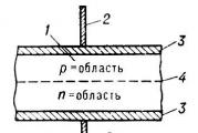
The picture shows the surface of the disk drive. Disk 2 surfaces. On each surface there are ring-shaped tracks (tracks). Each track is divided into small arcuate pieces, called sectors. So, historically it happened that the floppy sector has a size of 512 bytes. The very first sector on the disk, the boot sector, is read by the BIOS "Ohm in the zero memory segment by offset 0x7S00, and then the control is transmitted to this address. The initial loader usually loads in memory not the OS itself, but another program-loader stored on the disk, but For some reason (most likely, this reason is the size) is not climbing into one sector. And since it is so far the role of our OS is performing a banal hallowworeld, our main goal is to make the computer to believe in the existence of our OS, even if one sector, even in the same sector, And launch it.
How is the boot sector arranged? On the PC, the only requirement for the boot sector is the content in the two last bytes of the 0x55 and 0xaa values \u200b\u200b- the boot sector signatures. So, it is already more or less clear what we need to do. Let's write code! The given code is written for the YASM assembler.
Section .Text USE16 ORG 0x7C00; Our program is downloaded at 0x7c00 Start: MOV AX, CS MOV DS, AX; Select the MOV Si data segment, Message CLD; Direction for string commands MOV AH, 0x0e; BIOS MOV BH, 0x00 function number; Puts_loop: LODSB video memory page; We download the next character in Al Test Al, Al; zero symbol means the end of the row JZ PUTS_LOOP_EXIT INT 0X10; Call the BIOS JMP Puts_loop Puts_loop_Exit function: JMP $; Eternal Cycle Message: DB "Hello World!", 0 Finish: Times 0x1fe-FINISH + START DB 0 dB 0x55, 0xaa; Signature of the boot sector
This short program requires a number of important explanations. The ORG 0x7C00 string is needed in order for the assembler (meaning the program, not language) correctly calculated the address for tags and variables (Puts_loop, Puts_loop_exit, Message). Here we inform him that the program will be loaded into memory at 0x7c00.
In rows
MOV AX, CS MOV DS, AX
The data segment setting (DS) is set to an equal code segment (CS), because in our program and data, and the code is stored in one segment.
Next, the message "Hello World!" Is presented in the cycle. To do this, use the 0x0E interrupt function 0x0. It has the following parameters:
AH \u003d 0x0e (function number)
Bh \u003d video shirt number (not yet bother, point 0)
Al \u003d ASCII symbol code
In the "JMP $" string, the program freezes. And right, there is no need to fulfill the extra code. However, that the computer will have earned again, you will have to reboot.
In the "Times 0x1fe-Finish + Start DB 0" string, the remainder of the program code (with the exception of the last two bytes) zeros is made. This is done so that after compiling in the last two bytes of the program, the boot sector signature was the signature.
With the code code, it seems to deal with, let's now try to compile this happiness. To compile, we will need, actually assembler - the above mentioned YASM. It is in most Linux repository. The program can be compiled as follows:
$ YASM -F BIN -O Hello.bin Hello.asm
The resulting Hello.bin file needs to be written to the freezing sector of the floppy disk. It is done by about this (of course, instead of FD, you need to substitute the name of your drive).
$ dd if \u003d hello.bin of \u003d / dev / fd
Because everyone else has drives and diskettes, you can use a virtual machine, such as QEMU or VirtualBox. To do this, you will have to make an image of a floppy disk with our bootloader and insert it into the "Virtual Drive".
Create a disk image and fill it with zeros:
$ dd if \u003d / dev / zero of \u003d disk.img bs \u003d 1024 count \u003d 1440
We write on the very beginning of the image of our program:
$ dd if \u003d hello.bin of \u003d disk.img conv \u003d notrunc
Run the resulting image in QEMU:
$ qmu -fda disk.img -boot a
After starting, you should see the QEMU window with a joyful line "Hello World!". On this, the first article ends. We will be glad to see your feedback and wishes.
What you need to know to write an operating system
Creating an operating system is one of the most complex tasks in programming, because it requires extensive and integrated knowledge of the computer. Which ones? We understand below.
What is OS.
The operating system (OS) is a software that works with computer glands and its resources and is a bridge between the hardware and software part of the computer.
The first generation computers did not have operating systems. Programs on the first computers included code for the direct operation of the system, communication with peripheral devices and calculations, to execute this program and wrote. Because of this scenario, even simple software logic has been complex in software implementation.
As computers became more diverse and complex, write programs that worked as OS, and as an application, it was simply inconvenient. Therefore, that the programs make it easier to write, computer owners began to develop software. So the operating systems appeared.
The OS provides everything you need to work for user programs. Their appearance meant that now programs do not need to control the entire volume of the computer (this is an excellent example of encapsulation). Now the programs needed to work with the operating system, and the system itself cared for resources and operation with the periphery (keyboard, printer).
Briefly about the history of operating systems
CA Language
As mentioned above, there are several high-level programming languages \u200b\u200bfor writing OS. However, the most popular of them is si.
Start studying this language can be from here. This resource will introduce you to basic concepts and will prepare for more complex tasks.
"Learn C The Hard Way" - the name of another book. In addition to the usual theory, many practical solutions were collected in it. This tutorial will tell about all aspects of the language.
Or you can choose one of these books:
- "The C Programming Language" Kernighan and Ritchee;
- "C Programming Absolute Beginner's Guide" Parry and Miller.
Development of OS.
After the development of all necessary, as for informatics, the assembler language and Cy, you should read at least one or two books about the direct development of the OS. Here are some resources for this:
"Linux From Scratch". Here the process of assembling the Linux operating system is considered (the textbook is translated into many languages, including Russian). Here, as in other textbooks, you will be provided with all the necessary basic knowledge. Relying on them you can try yourself in creating OS. To make the software part of the OS more professional, there are additions to the textbook: "
Author Vulf Gamer. asked a question in the section Other languages \u200b\u200band technologies
How to create your own OS? And got the best answer
Answer from Alexander Bagrov [Guru]
The idea is commendable.
First of all, you need to know the system of the machine commands for which you intend to write OS.
The system system finds its direct reflection in the assembler language.
Therefore, first of all you need to come up with your own language of the assembler and write a program for him (assembler), broadcasting alphanumeric symbolism into the machine
the code.
If interesting, you can see what kind of requirements should have a new (perfect) OS.
Some such features are listed here:
.ru / d_os / os-poolym.html # idealos
It is necessary to study materials of microprocessor site developers. For example, Intel and AMD.
You may be useful for you a video course of lectures on the OS, which is presented here:
.ru / d_os / os_general.html
PS: Do not listen to pessimists. Proceed from the ideology of a rooster, chasing a chicken:
"Do not catch up, at least warm up."
Source: Site "Use PCs correctly!"
Answer from 2 response[guru]
Hey! Here is a selection of topics with answers to your question: How to create your own OS?
Answer from Vadim Hprlamov[newcomer]
Of course), there is some gates sitting) on \u200b\u200bMicrosoft ask)
Answer from Irina Starodubseva[newcomer]
take all OS and in one hole
Answer from Alexander Tuntsov[guru]
Check out Linux OS, learns programming and on the road
Answer from ~ In Flames ~[guru]
Programming to learn at the highest level, collect a whole crowd of the same computer geniuses and then you can already do.
Answer from Rasul Magomedov.[guru]
Start with the creation of mischievous wallpaper
Answer from Captain Google[guru]
About "10 years to explore the basics" - do not listen, Torvalds wrote the first version of Linux at 22, and his computer appeared in 12. As you understand, he not only studied the basics.
Start with the study of the already existing one - on the one hand, the "modern operating systems" of Tannenbauma, on the other hand, bring Linux from Scratch, with the third - learn Assembler, C, C ++. For everything about everything - you can meet in 3-4 years. After that, you can start developing your system ... If you still want.
Answer from Yuan Semenov[guru]
do you know how did Gates did? Try the same, they say profitably happens ..
When his parents punished, he from nothing to do began to jump on the clave, then sold to calling what happened "Windows"
P with and if you really write at first "Hello World" in C ++ and immediately understand that the idea is paranoid
Answer from Kostafey.[guru]
What for? What fundamentally do not suit existing? Is there any one, at least partially satisfying your requirements for the OS? Maybe it's worth it better to join the team of the developers? It will be 100500 times a sense.
And then, you abandon this idea by another 0, (0) 1% of its implementation.
Answer from Evgeny Lita[guru]
E. Tannbaum "Operating Systems: Development and Sales"
good luck
PS Unfortunately, how did Bill Gates do, you are unlikely to succeed. His mother is a cool banker, you have?
Answer from Krab Bark.[guru]
You can write the simplest OS, but it will not be able to compete with the OS like Windows, Mac OS or Linux, over which hundreds of or thousands of programmers worked at least dozen years. In addition, OS is only the foundation. It is necessary that the developers of the equipment wrote their drivers for this OS, the developers of application programs wrote editors, players, browsers, games, features in a step ... And without this OS will remain anyone who does not need the foundation for the house, which no one will build.
Answer from Vadim Stakhanov[active]
It would be better if the philologist would have learned. And then I would shout out "Free Cashier!"
Answer from \u003d Serge \u003d.[guru]
Hooray! Finally, 58 Question on the site about the creation of "your" OS))
Here are questions about "Write your OS" - their only 34))
Read .... 92 questions * 10 replies \u003d approximately 920 replies))
At the same time, it is possible to understand what they mean "miscarriages")).
Answer from Irreproducible.[guru]
another Denis Popov with the next Bolgenos "Ohm?
Answer from Ivan Tatarchuk[newcomer]
lauce notepad download Zhabaspte compiler and start jumping boo on keyboard
after 60 minutes compile and all
your Oska is ready
Answer from Sheep Mila[newcomer]
OS? Which exactly? OS-BORIZHINAL Chester (original character (translated))
She needs an impending image of himself cartoons or films.
1. Invent what particular cartoon / movie you want OS
2. Consider the style of cartoon / movie
3. Who will be your character (fairy, pony, magician, robot, etc.)
4. Describe it mentally, then on paper
5. Find up design
6. Invent the name and bio
7. Draw a character!
8. Now for business with Paint Tud Sai
Original: "Roll Your Own Toy Unix-Clone OS"
Posted by: James Molloy
Publication date: 2008
Translation: N.Romodanov
Translation Date: January 2012
This manual set is designed to show you in detail how to program a simple UNIX-like operating system for the X86 architecture. In these manuals, the C language is selected as a programming language, which is complemented by the assembler language where it is required. The purpose of the manuals is to tell you about the development and implementation of solutions used when creating an OS operating system, which we create, monolithic by their structure (drivers are loaded in the kernel modules mode, and not in user mode as happening with the programs), since such a solution More simple.
This set of manuals is very practical in nature. Each section provides theoretical information, but most of the leadership concerns the issues of implementation in the practice of the considered abstract ideas and mechanisms. It is important to note that the kernel is implemented as a training. I know that the algorithms used are neither the most effective on the use of space or optimal. They are usually chosen due to their simplicity and ease of understanding. The purpose of this is to give you the right attitude and provide the basis on which you can work. This kernel is extensive and you can easily connect the best algorithms. If you have problems related to theory, that is, many sites where you will help you deal with it. Most of the issues discussed on the OSDEV forum relate to the implementation ("My Gets Function Doesn" T Work! Help! "/" My function does not work! Help! ") And for many, the question about theory is similar to the sip of fresh air. Links can be found in late present introduction.
Preliminary preparation
To compile and run the code with examples, as I assume, you will need only GCC, LD, NASM and GNU Make. NASM is an assembler for X86 open source and many OS developers for the X86 platform are chosen by it.
However, there is no point in the compilation and run examples, if there are no understanding. You must understand what is encoded, and for this you need to know very well a language C, especially what concerns the pointers. You must also understand the assembler slightly (in these manuals use Intel syntax), including what the EBP register is used.
Resources
There are many resources if you know how to find them . In particular, the following links will be useful for you:
- RTFM! Intel's manuals are a find.
- Wiki Pages and Forums Website Osdev.org.
- On OsDever.net, there are many good guides and articles and, in particular, Bran "S Kernel Development Tutorials (kernel development guide), on the earlier code of which this manual is based. I used these guides in order to start work, And the code in them was so good that I did not change it for a number of years.
- If you are not new, then you can get answers to many questions in the group
The development of the kernel is considered to be a task not from the lungs, but to write the simplest core can each. To touch the magic of Kernel-Hucking, you only need to keep some conventions and cope with the assembler. In this article we will analyze on your fingers how to do it.
Hello World!
Let's write the kernel that will be loaded through GRUB on X86 compatible systems. Our first kernel will show the message on the screen and stop on it.
How the X86 machines are loaded
Before thinking about how to write the kernel, let's see how the computer is loaded and transfers the control of the kernel. Most X86 processor registers have certain values \u200b\u200bafter loading. Register - pointer to the instruction (EIP) contains the address of the instruction that will be executed by the processor. Its sweeping value is 0xFFFFFFF0. That is, the X86th processor will always start execution from the physical address 0xFFFFFFF0. This is the last 16 bytes of 32-bit targeted space. This address is called "RESET CEECTOR).
The memory card contained in the chipset is written that the address 0xFFFFFFF0 refers to a specific part of the BIOS, and not for RAM. However, BIOS copies themselves to the RAM for faster access - this process is called "Shadowing), creating a shadow copy. So the address 0xFFFFFFF0 will only contain the transition instructions to the place in memory where BIOS copied itself.
So, BIOS begins to execute. First, it is looking for devices from which you can download in the order that is specified in the settings. It checks the carriers for the presence of a "magic number", which distinguishes the boot discs from ordinary: if bytes 511 and 512 in the first sector are 0xaA55, it means that the boot disk.
As soon as the BIOS finds a boot device, it copies the contents of the first sector to the RAM, starting with the address 0x7c00, and then translates the execution to this address and the execution of the code that has just downloaded. This code is called the bootloader (BOOTLOADER).
The bootloader loads the kernel on the physical address 0x100000. It is he who is used by most popular kernels for x86.
All X86 compatible processors begin their work in a primitive 16-bit mode, which is called the "real mode" (Real Mode). The GRUB loader switches the processor to 32-bit protected mode (Protected Mode), translating the lower bit of the CR0 register to one. Therefore, the kernel begins to load already in a 32-bit protected mode.
Note that the GRUB in the case of Linux kernels selects the appropriate download protocol and loads the kernel in real mode. Linux kernels themselves switch to secure mode.
What we need
- X86 compatible computer (obviously)
- Linux,
- assembler NASM,
- lD (GNU LINKER),
- Grub.
Input point on assembler
We would, of course, wanted to write everything on C, but to completely avoid using the assembler will not work. We will write a small file on the X86 assembler, which will be the starting point for our kernel. Everything that assembler code will make is to cause an external function that we will write on C, and then stop the program.
How to make the assembler code be the starting point for our core? We use a linker script (LINKER), which links object files and creates the final executable kernel file (explain in more detail below). In this script, we directly indicate that we want our binary file to load at 0x100000. This address, as I wrote, through which the bootloader expects to see the input point in the kernel.
Here is the code on the assembler.
kernel.asm.
Bits 32 Section .text Global Start Extern KMAIN START: CLI MOV ESP, Stack_Space Call KMAIN HLT Section .Bss Resb 8192 stack_space:The first BITS 32 instruction is not an X86 assembler, but a NASM directive reporting that you need to generate a code for a processor that will work in 32-bit mode. For our example, this is not necessarily, but it is clearly indicative - good practice.
The second string starts the text section, also known as the code section. This will go here all our code.
global is another NASM directive, it declares characters from our code global. This will allow the linker to find the Start symbol, which serves our input point.
kMAIN is a function that will be defined in our kernel.c file. Extern announces that the function is declared somewhere else.
Next, the Start function is running, which causes KMAIN and stops the processor with the HLT instruction. Interrupts can be wake-up processor after HLT, so first we turn off the interrupts of the CLI instruction (Clear Interrupts).
Ideally, we must allocate some number of memory under the stack and send the stack (ESP) pointer to it. GRUB, it seems, it does it for us, and at this moment the stack pointer is already set. However, just in case, select a few memory in the BSS section and send the stack pointer to its beginning. We use the RESB instruction - it reserves the memory specified in bytes. Then the label is left, indicating the edge of the reserved piece of memory. Directly before calling the KMAIN, the stack pointer (ESP) is sent to this area by the MOV instruction.
Core on C.
In the kernel.asm file, we called the KMAIN () function. So in the code on c, the execution will begin with it.
kernel.c.
Void KMAIN (Void) (Const charnel "; char * vidptr \u003d (char *) 0xb8000; unsigned int i \u003d 0; unsigned int j \u003d 0; while (j< 80 * 25 * 2) { vidptr[j] = " "; vidptr = 0x07; j = j + 2; } j = 0; while(str[j] != "\0") { vidptr[i] = str[j]; vidptr = 0x07; ++j; i = i + 2; } return; }Everything that our core will do is clear the screen and display the MY FIRST Kernel string.
First of all, we create a VIDPTR pointer, which indicates 0xB8000 address. In a secure mode, this is the beginning of video memory. Text screen memory is just part of the address space. Under the on-screen entry-output, a memory area that starts with the address of 0xB8000 is allocated - 25 lines of 80 ASCII characters are placed in it.
Each symbol in text memory is represented by 16 bits (2 bytes), and not 8 bits (by 1 byte) to which we are accustomed. The first byte is a symbol code in ASCII, and the second byte is attribute-byte. This is determining the symbol format, including its color.
To withdraw the S symbol with green in black, we need to put S in the first byte of the video memory, and the value of 0x02 in the second byte. 0 Here means a black background, and 2 - green. We will use light gray color, its code - 0x07.
In the first WHILE cycle, the program fills empty characters with an attribute 0x07 all 25 rows of 80 characters. This will clean the screen.
In the second WHILE cycle, the symbols of the My first Kernel string, an end with a zero symbol, are recorded in the video memory and each character gets an attribute-byte equal to 0x07. This should lead to the conclusion of the string.
Layout
Now we must collect kernel.asm to the object file using NASM, and then using the GCC to compile kernel.c to another object file. Our task is to lick these objects in the executable core, suitable for download. To do this, you will need to write a script for a linker (LD), which we will transmit as an argument.
link.ld.
Output_format (ELF32-i386) Entry (Start) sections (. \u003d 0x100000; .Text: (* (. Text)) .data: (* (. Data)) .Bss: (* (BSS)))Here we first specify the format (Output_format) of our executable file as a 32-bit ELF (Executable and Linkable Format), a standard binary format for UNIX-shaped systems for the X86 architecture.
Entry takes one argument. It specifies the name of the symbol that will serve as an input point of the executable file.
Sections are the most important part for us. Here we define the layout of our executable file. We can determine how different sections will be combined and where each of them will be placed.
In curly brackets, which go beyond the expression sections, the point means the position counter (Location Counter). It is automatically initialized by the 0x0 value at the beginning of the Sections block, but it can be changed by assigning a new value.
Earlier, I already wrote that the kernel code should begin at 0x100000. That is why we assign a value to 0x100000 position counter.
Look at the string.Text: (* (. Text)). An asterisk here is the mask, which is suitable for any name of the file. Accordingly, the expression * (. Text) means all input sections .Text in all input files.
As a result, the linker will slighten all the text sections of all object files into the text section of the executable file and will be placed at the address specified in the position meter. The code section of our executable file will start at 0x100000.
After the linker displays the text section, the position counter value will be 0x100000 plus the size of the text section. Similarly, the DATA and BSS sections will be merged and placed at the address set by the position counter.
GRUB and Multi-load
Now all our files are ready to assemble the kernel. But since we will download the kernel with GRUB, one step remains.
There is a standard for downloading different x86 nuclei with a bootloader. This is called the "Multibut Specification". GRUB will only download those kernels that match it.
In accordance with this specification, the kernel may contain a header (MultiBoot Header) in the first 8 kilobytes. Three fields should be spelled out in this header:
- magic. - contains a "magic" number 0x1Badb002, which is identified by the title;
- flags. - This field is not important for us, you can leave zero;
- checksum. - The checksum must give zero if adding it to the Magic and Flags fields.
Our kernel.asm file will now look as follows.
kernel.asm.
Bits 32 Section .text; Multiboot Spec Align 4 DD 0x1Badb002; Magic DD 0x00; Flags DD - (0x1Badb002 + 0x00); Checksum Global Start Extern KMain Start: CLI MOV ESP, Stack_Space Call KMAIN HLT Section .Bss Resb 8192 stack_space:DD instruction sets a dual word 4 byte size.
We collect kernel
So, everything is ready in order to create an object file from kernel.asm and kernel.c and linking them using our script. We write in the console:
$ NASM -F ELF32 Kernel.asm -o Kasm.o
For this command, the assembler will create a kasm.o file in ELF-32 BIT format. Now the GCC turn came:
$ gcc -m32 -c kernel.c -o kc.o
The -c parameter indicates that the file after compilation does not need to be linked. We will do it yourself:
$ LD -M Elf_i386 -t Link.ld -o Kernel Kasm.o Kc.O
This command will start the linker with our script and will generate an executable file called Kernel.
Warning
Hacking kernel is best practiced in a virtual. To start the kernel in QEMU instead of GRUB, use the qemu-system-i386 -kernel kernel command.
Customize Grub and launch the kernel
GRUB requires that the name of the file with the kernel follows the Kernel Convention<версия> . So rename the file - I will call my kernel-701.
Now put the kernel in the / boot directory. This will require the privileges of the superuser.
In the Grub.cfg configuration file, you will need to add something in such a way:
Title Mykernel Root (HD0,0) Kernel / Boot / Kernel-701 Ro
Do not forget to remove the Hiddenmenu directive if it is spelled out.
Grub 2.
To start the core created by us in Grub 2, which is supplied by default in new distributions, your config should look as follows:
MENUENTRY "KERNEL 701" (Set root \u003d "HD0, MSDOS1" MULTIBOOT / BOOT / KERNEL-701 RO)
I thank Ruban Laguan for this addition.
Restart the computer, and you will have to see your kernel in the list! And choosing it, you will see that very line.

This is your kernel!
We write kernel with keyboard and screen support
We finished work on the minimum core, which is loaded through GRUB, works in secure mode and displays one line to the screen. It is time to extend it and add a keyboard driver that will read the characters from the keyboard and display them on the screen.
We will communicate with I / O devices through I / O ports. In essence, they are just addresses on the I / O bus. For read and write operations, there are special processor instructions.
Working with ports: Reading and Conclusion
Read_Port: MOV EDX, in AL, DX RET WRITE_PORT: MOV EDX, MOV AL, OUT DX, AL RETAccess to I / O ports is carried out using In and Out instructions included in the X86 set.
In read_port, the port number is transmitted as an argument. When the compiler calls the function, it puts all the arguments on the stack. The argument is copied to the EDX register with the pointer to the stack. The DX register is the lower 16 EDX bits. Instructions in Here reads the port, the number of which is set in the DX, and puts the result in Al. The Al register is the lower 8 bits of the EAX register. Perhaps you remember from the institute course that the values \u200b\u200breturned by the functions are transmitted through the EAX register. Thus, read_port allows us to read from I / O ports.
The WRITE_PORT function works in a similar way. We accept two arguments: port number and data that will be recorded. OUT instruction writes data to the port.
Interrupts
Now, before we return to writing the driver, we need to understand how the processor learns that some of the devices performed the operation.
The simplest solution is to interrogate the devices - continuously check their status in a circle. This is obvious reasons ineffective and impractical. Therefore, there are interruptions in the game. Interrupt is a signal sent by the processor by a device or a program that means an event occurred. Using interrupts, we can avoid the need to interrogate the devices and will respond only to the events you are interested in.
For interrupts in the architecture of the X86 corresponds to the chip called Programmable Interrupt Controller (PIC). It processes hardware interrupts and sends and turns them into the appropriate system interrupts.
When the user does something with the device, the PIC chip is sent by a pulse called Interrupt Request, IRQ. PIC translates the resulting interrupt in the system interruption and sends a message processor that it's time to stop what it does. Further processing of interrupts is the kernel task.
Without PIC, we would have to poll all the devices present in the system to see if an event happened with some of them.
Let's wonder how it works in the case of the keyboard. The keyboard is hanging on ports 0x60 and 0x64. Port 0x60 gives data (when some button is pressed), and port 0x64 transmits status. However, we need to know when specifically read these ports.
Interrupts here come as it is impossible to more by the way. When the button is pressed, the keyboard sends the PIC signal over the IRQ1 interrupt line. PIIC stores the value of Offset, saved during its initialization. It adds the input number to this retirement to form the interrupt vector. The processor is then looking for a data structure called "Interrupt Table" (Interrupt Descriptor Table, IDT) to give a function - an interrupt handler address corresponding to its number.
Then the code is executed at this address and processes interrupt.
Specify IDT.
STRUCT IdT_ENTRY (unsigned short int offset_lowerbits; unsigned short int selector; unsigned char zero; unsigned char type_attr; unsigned short int offset_higherbits;); Struct IDT_ENTRY IDT; void idt_init (void) (unsigned long keyboard_address; unsigned long idt_address; unsigned long idt_ptr; keyboard_address \u003d (unsigned long) keyboard_handler; IDT.offset_lowerbits \u003d keyboard_address & 0xffff; IDT.selector \u003d 0x08; / \u200b\u200b* KERNEL_CODE_SEGMENT_OFFSET * / IDT.zero \u003d 0 ; IDT.Type_attr \u003d 0x8e; / * interrupt_gate * / IDT.OFFSET_HIGHERBITS \u003d (keyboard_address & 0xfff0000) \u003e\u003e 16; write_port (0x20, 0x11); write_port (0xa0, 0x11); write_port (0x21, 0x20); write_port (0xa1, 0x28); write_port (0x21, 0x00); write_port (0xa1, 0x00); write_port (0x21, 0x01); write_port (0xa1, 0x01); write_port (0x21, 0xFF); write_port (0xa1, 0xFF); IDT_ADDRESS \u003d (unsigned long ) IDT; IDT_PTR \u003d (SizeOF (struct IDT_ENTRY) * IDT_SIZE) + ((IDT_ADDRESS & 0XFFFF)<< 16); idt_ptr = idt_address >\u003e 16; Load_idt (IDT_PTR); )IDT is an array that combines IDT_ENTRY structures. We will also discuss the binding of the keyboard interrupt to the handler, and now let's see how PIC works.
Modern X86 systems have two PIC chip, each eight input lines. We will call them pic1 and pic2. Pic1 receives from IRQ0 to IRQ7, and PIC2 - from IRQ8 to IRQ15. PIC1 uses port 0x20 for commands and 0x21 for data, and PIC2 is port 0xa0 for commands and 0xa1 for data.
Both PIC are initialized by eight-bit words that are called "Initialization Commands" (Initialization Command Words, ICW).
In protected mode, both PIC first need to give the initialization command ICW1 (0x11). She informs PIC that you need to wait for three more initialization words that will come to the data port.
These commands will pass PIC:
- vector retirement (ICW2),
- what are between PIC Master / Slave relationship (ICW3),
- additional environmental information (ICW4).
The second initialization command (ICW2) also stars to enter each PIC. It assigns offset, that is, the value to which we add the line number to get the interrupt number.
PIC Allow cascade redirection of their conclusions to each other's entry. This is done using ICW3, and each bit represents cascade status for the corresponding IRQ. Now we will not use cascade redirection and exhibit zeros.
ICW4 sets additional environmental parameters. We need to define only the bottom bit so that the PIC knew, that we work in the 80x86 mode.
Ta-lad! Now PIC is initialized.
Each PIC has an internal eight-bit register, which is called "Interrupt Mask Register, IMR). It stores the bitmap of IRQ lines, which go to PIC. If the bit is specified, PIC ignores the query. This means that we can enable or turn off the defined IRQ line by setting the corresponding value to 0 or 1.
Reading from the port port returns a value in the IMR register, and the record changes the register. In our code after initializing PIC, we set all bits per unit than deactivate all IRQ lines. Later we activate the lines that correspond to keyboard interrupts. But for starters, still turn off!
If IRQ lines work, our PICs can receive IRQ signals and convert them to the interrupt number by adding offset. We need to fill the IDT in such a way that the interrupt number that came from the keyboard corresponds to the address of the handler function that we will write.
What number of interrupts do we need to tie the keyboard handler in the IDT?
The keyboard uses IRQ1. This is the input line 1, it processes PIC1. We initialized PIC1 with offset 0x20 (see ICW2). To get the interrupt number, you need to fold 1 and 0x20, it will turn out 0x21. So, the keyboard handler address will be tied to IDT to interrupt 0x21.
The task is reduced to complete the IDT for interrupting 0x21. We will climb this interruption to the Keyboard_Handler function, which we will write in the assembler file.
Each entry in IDT consists of 64 bits. In the recording corresponding to the interrupt, we do not save the address of the handler function entirely. Instead, we divide it into two parts of 16 bits. The lower bits are saved in the first 16 entry bits in IDT, and the older 16 bits in the last 16 recording bits. All this is done for compatibility with 286-processors. As you can see, Intel highlights such numbers on a regular basis and in many-many places!
In the IDT entry, we left to register the type, indicating that all this is done to catch the interrupt. We still need to ask an offset segment of the coder code. GRUB Specifies GDT for us. Each GDT entry has a length of 8 bytes, where the kernel code descriptor is the second segment, so that its offset will be 0x08 (the details do not fit into this article). Interrupt gate is represented as 0x8e. The remaining in the middle of 8 bits fill with zeros. Thus, we will fill in the IDT record, which corresponds to the keyboard interrupt.
When the IDT mapping will be finished, we will need to inform the processor where the IDT is located. To do this, there is an assembler instruction Lidt, it takes one operand. It serves as a pointer to the structure descriptor, which describes IDT.
With a descriptor no difficulties. It contains the IDT size in bytes and its address. I used an array to be compacting. Similarly, you can fill out a descriptor using the structure.
In the IDR_PTR variable, we have a pointer that we transmit the LIDT instructions in the Load_idt () function.
Load_idt: MOV EDX, Lidt Sti Ret
Additionally, the Load_idt () function returns an interrupt when using the STI instruction.
By completing and downloading IDT, we can refer to the IRQ keyboard using the interrupt mask, which we have said earlier.
Void kb_init (void) (Write_Port (0x21, 0xfd);)
0xfd is 11111101 - we turn on only IRQ1 (keyboard).
Function - keyboard interrupt handler
So, we successfully tied the keyboard interruption to the Keyboard_Handler function by creating an IDT entry for interrupting 0x21. This feature will be called every time you click on any button.
Keyboard_Handler: Call Keyboard_Handler_Main iRetd
This feature calls another function written in C, and returns control using the IRET class instructions. We could write our entire handler here, but it is much easier to drive on C, so rolling back there. The IRET / IRETD instructions must be used instead of RET when control returns from a function processing, to the program, the execution of which it was interrupted. This class of instructions raises the flag register, which enters the stack when calling interrupts.
Void keyboard_handler_main (void) (unsigned char status; char keycode; / * write eoi * / write_port (0x20, 0x20); status \u003d read_port (keyboard_status_port); / * Lower status bit will be set, if the buffer is not empty * / if (Status & 0x01) (Keycode \u003d read_port (keyboard_data_port); if (keycode< 0) return; vidptr = keyboard_map; vidptr = 0x07; } }
Here we first give an EOI (End of Interrupt, ending the interrupt processing) by writing it to the PIC command port. Only after that PIC will allow further interruption requests. We need to read two ports: data port 0x60 and command port (it is Status Port) 0x64.
First of all read the port 0x64 to get status. If the bottom bit of status is zero, it means that the buffer is empty and there is no reading data. In other cases, we can read the data port of 0x60. It will give us the code by pressing the key. Each code corresponds to one button. We use a simple character array specified in the keyboard_map.h file to tie codes to the corresponding characters. Then the character is displayed on the screen with the same equipment that we used in the first version of the kernel.
In order not to complicate the code, I only process the lowercase letters from A to Z and the numbers from 0 to 9. You can easily add specialsters, Alt, Shift and Caps Lock. To find out that the key is pressed or released, from the output of the command port and perform the appropriate action. Similarly, you can bind any key combinations to special functions like shutdown.
Now you can collect the kernel, run it on a real machine or on the emulator (QEMU) as well as in the first part.