Diagram for a homemade matrix oscilloscope. Homemade oscilloscope input nodes
An oscilloscope is a portable device designed for testing microcircuits. Additionally, many models are suitable for industrial control and can be used for various measurements. It is impossible to make an oscilloscope with your own hands without a zener diode, which is its main element. This part is installed in a device of various powers.
Additionally, devices, depending on the modification, may include capacitors, resistors and diodes. The main parameters of the model include the number of channels. Depending on this indicator, the limiting bandwidth changes. Also, when assembling an oscilloscope, consider the sampling rate and memory depth. In order to analyze the received data, the device is connected to a personal computer.
Simple oscilloscope circuit
A simple oscilloscope circuit includes a 5 V zener diode. Its bandwidth depends on the types of resistors that are installed on the microcircuit. Capacitors are used to increase the vibration amplitude. You can make a probe for an oscilloscope with your own hands from any conductor. In this case, the port is selected separately in the store. Resistors of the first group must withstand the minimum resistance in the circuit at a level of 2 ohms. Moreover, the elements of the second group should be more powerful. It should also be noted that there are diodes on the circuit. In some cases, they line up as bridges.

Single channel model
It is possible to make a single-channel digital oscilloscope with your own hands only using a 5 V zener diode. In this case, more powerful modifications are unacceptable in this case. This is due to the fact that an increased limit voltage in the circuit leads to an increase in the sampling rate. As a result, the resistors in the device fail. Capacitors for the system are selected only of the capacitive type.
The minimum resistor must keep the resistance at 4 ohms. If we consider the elements of the second group, then the transmission parameter in this case should be 10 Hz. In order to raise it to the desired level, various types of regulators are used. Some experts recommend using orthogonal resistors for single-channel oscilloscopes.
In this case, it should be noted that they raise the sampling rate indicator rather quickly. However, negative aspects in such a situation are still present, and they should be taken into account. First of all, it is important to note the sharp excitation of oscillations. As a result, the asymmetry of the signals increases. Additionally, there are problems with the sensitivity of the device. Ultimately, the accuracy of the readings may not be the best.

Dual channel devices
It is quite difficult to make a two-channel oscilloscope with your own hands (the diagram is shown below). First of all, it should be noted that zener diodes in this case are suitable for both 5 V and 10 V. In this case, capacitors for the system must be used only of a closed type.
Due to this, the bandwidth of the device can be increased to 9 Hz. Resistors for the model, as a rule, are of the orthogonal type. In this case, they stabilize the signal transmission process. To perform the functions of addition, microcircuits are selected mainly of the MMK20 series. You can make a divider for an oscilloscope with your own hands from a conventional modulator. It's not particularly difficult.

Multichannel modifications
In order to assemble a USB oscilloscope with your own hands (the diagram is shown below), a Zener diode will need a rather powerful one. The problem in this case is to increase the bandwidth of the circuit. In some situations, the resistors may malfunction due to a change in the limiting frequency. In order to solve this problem, many people use auxiliary divisors. These devices do a lot to help raise the voltage limit.
The divider can be made using a modulator. The capacitors in the system must be installed only near the zener diode. Analog resistors are used to increase the bandwidth. The negative resistance parameter on average fluctuates around 3 ohms. The blocking range depends solely on the power of the zener diode. If the limiting frequency drops sharply when the device is turned on, then the capacitors must be replaced with more powerful ones. Some experts in this case advise to install diode bridges. However, it is important to understand that the sensitivity of the system in this situation deteriorates significantly.
Additionally, you need to make a probe for the device. In order for the oscilloscope not to conflict with a personal computer, it is more expedient to use an MMP20 type microcircuit. You can make a probe from any conductor. In the end, a person will only have to acquire a port for him. Then, using a soldering iron, the above elements can be connected.

Assembling a 5V device
At 5 V, a do-it-yourself oscilloscope-set-top box is made only using an MMP20 type microcircuit. It is suitable for both conventional and high-power resistors. The maximum resistance in the circuit should be 7 ohms. In this case, the bandwidth depends on the signal transmission rate. Dividers for devices can be used in a variety of ways. Today, static analogs are considered to be more common. The bandwidth in such a situation will be at around 5 Hz. To increase it, you need to use tetrodes.
They are selected in the store, based on the parameter of the limiting frequency. To increase the amplitude of the reverse voltage, many experts advise installing only self-regulating resistors. In this case, the signal transmission rate will be quite high. At the end of the work, you need to make a probe to connect the circuit to a personal computer.
10 V oscilloscopes
A do-it-yourself oscilloscope is made with a zener diode, as well as closed-type resistors. If we consider the parameters of the device, then the vertical sensitivity indicator should be at the level of 2 mV. Additionally, the bandwidth should be calculated. For this, the capacitance of the capacitors is taken and correlated with the limiting resistance of the system. The resistors for the device are most suitable for the field type. To minimize the sampling rate, many experts advise using only 2 V diodes. Due to this, a high signal transmission rate can be achieved. In order for the tracking function to be performed rather quickly, microcircuits are installed of the MMP20 type.
If you plan storage and playback modes, then you need to use a different type. Cursor measurements in this case will be unavailable. The main problem with these oscilloscopes can be considered a sharp drop in the limiting frequency. This is due, as a rule, to a quick sweep of the data. The task can be solved only with the use of a high-quality divider. That being said, many also rely on a zener diode. The divider can be made using a conventional modulator.

How to make a 15V model?
The oscilloscope is assembled with your own hands using linear resistors. They are able to withstand the ultimate resistance at the level of 5 mm. Due to this, there is not much pressure on the Zener diode. Additionally, you should take care of the selection of capacitors for the device. For this purpose, it is necessary to make measurements of the threshold voltage. Specialists use a tester for this.
If you use tuning resistors for the oscilloscope, you may encounter increased vertical sensitivity. Thus, the data obtained as a result of testing may be incorrect. Considering all of the above, it is necessary to use only linear analogs. Additionally, you should take care of installing a port that is connected in the microcircuit through a probe. In this case, it is more expedient to install the divider through the bus. So that the vibration amplitude is not too large, many advise using vacuum-type diodes.
Using resistors of the PPR1 series
Making a USB oscilloscope with your own hands with these resistors is not an easy task. In this case, it is necessary first of all to evaluate the capacitance of the capacitors. In order to keep the voltage limit below 3 V, it is important to use no more than two diodes. Additionally, remember the nominal frequency parameter. On average, this figure is 3 Hz. Orthogonal resistors are not suitable for such an oscilloscope unambiguously. Construction changes can only be made using the divider. At the end of the work, you need to deal with directly installing the port.
Models with PPR3 resistors
You can make a USB oscilloscope with your own hands using only grid capacitors. Their peculiarity lies in the fact that the level of negative resistance in the circuit can reach 4 ohms. A wide variety of microcircuits are suitable for such oscilloscopes. If we take the standard version of the MMP20 type, then it is necessary to provide at least three capacitors in the system.
Additionally, it is important to pay attention to the density of the diodes. In some cases, the bandwidth factor depends on it. To stabilize the fission process, experts advise to carefully check the conductivity of the resistors before turning on the device. Last of all, the regulator is connected directly to the system.

Oscillation suppression devices
Oscilloscopes with a vibration suppression unit are rarely used these days. They are most suitable for testing electrical appliances. Additionally, it should be noted their high vertical sensitivity. In this case, the parameter of the limiting frequency in the circuit should not exceed 4 Hz. Due to this, the Zener diode does not overheat much during operation.
A do-it-yourself oscilloscope is made using a grid-type microcircuit. In this case, it is necessary at the very beginning to determine the types of diodes. Many in this situation are advised to use only analog types. However, in this case, the signal transmission rate can be significantly reduced.
It is difficult for any radio amateur to imagine his laboratory without such an important measuring device as an oscilloscope. And, indeed, without a special tool that allows you to analyze and measure the signals acting in the circuit, the repair of most modern electronic devices is impossible.
On the other hand, the cost of these devices often exceeds the budgetary capabilities of an ordinary consumer, which forces him to look for alternative options or make an oscilloscope with his own hands.
Solutions to the problem
You can refuse to buy expensive electronic products in the following cases:
- Using for these purposes a sound card (ZK) built into a PC or laptop;
- DIY USB oscilloscope making;
- Refinement of a regular tablet.
Each of the options listed above, allowing you to make an oscilloscope with your own hands, is not always applicable. For full-fledged work with independently assembled consoles and modules, the following prerequisites must be met:
- The admissibility of certain restrictions on the measured signals (on their frequency, for example);
- Experience with complex electronic circuits;
- The ability to refine the tablet.
So, an oscilloscope from a sound card, in particular, does not allow measuring oscillatory processes with frequencies outside its operating range (20 Hz-20 kHz). And to make a USB set-top box to a PC, you will need some experience in assembling and configuring complex electronic devices (just like when connecting to a regular tablet).
Note! The option in which it is possible to make an oscilloscope from a laptop or tablet with the simplest approach comes down to the first case, which involves the use of a built-in ZK.
Let's consider how each of the above methods is implemented in practice.
Using ZK
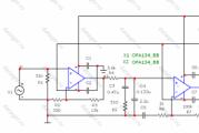
To implement this method of obtaining an image, it will be necessary to make a small-sized attachment, consisting of only a few electronic components available for each. Its diagram can be found in the picture below.

The main purpose of such an electronic circuit is to ensure the safe supply of an external signal under investigation to the input of a built-in sound card, which has its own analog-to-digital converter (ADC). The semiconductor diodes used in it guarantee the limitation of the signal amplitude to no more than 2 volts, and the divider of resistors connected in series allows supplying voltages with large amplitude values to the input.

A wire with a 3.5 mm plug on the opposite end is soldered to the board with resistors and diodes from the output side, which is inserted into the ZK socket under the name "Line In". The signal under investigation is applied to the input terminals.
Important! The length of the connecting cord should be as short as possible to ensure minimal signal distortion at very low measured levels. It is recommended to use a two-core wire with a copper braid (screen) as such a connector.
Although the frequencies passed by such a limiter belong to the low frequency range, this precaution helps to improve the transmission quality.
Program for obtaining oscillograms
In addition to technical equipment, before starting measurements, you should prepare the appropriate software (software). This means that you need to install one of the utilities on your PC, designed specifically for obtaining an image of the waveform.

Thus, in just an hour or a little more, it is possible to create conditions for the study and analysis of electrical signals using a stationary PC (laptop).
Refinement of the tablet
Using the built-in map
In order to adapt a regular tablet for recording oscillograms, you can use the previously described method of connecting to the audio interface. In this case, certain difficulties are possible, since the tablet does not have a discrete line-in for a microphone.
This problem can be solved as follows:
- You need to take a headset from the phone, which should include a built-in microphone;
- Then you should clarify the wiring (pinout) of the input terminals on the tablet used for connection and compare it with the corresponding contacts on the headset plug;
- If they match, you can safely connect a signal source instead of a microphone, using the previously discussed attachment on diodes and resistors;
- In the end, it remains to install a special program on the tablet that can analyze the signal at the microphone input and display its graph on the screen.
The advantages of this method of connecting to a computer are ease of implementation and low cost. Its disadvantages include a small range of measured frequencies, as well as the lack of a 100% security guarantee for the tablet.
These drawbacks can be overcome through the use of special electronic set-top boxes connected via a Bluetooth module or via a Wi-Fi channel.
Homemade set-top box for Bluetooth-module
Connection via "Bluetooth" is carried out using a separate gadget, which is a prefix with an ADC microcontroller built into it. Due to the use of an independent information processing channel, it is possible to expand the bandwidth of the transmitted frequencies to 1 MHz; in this case, the value of the input signal can reach 10 volts.
Additional Information. The radius of action of such a self-made attachment can reach 10 meters.
However, not everyone is capable of assembling such a conversion device at home, which significantly limits the range of users. For all those who are not ready for independent production of the set-top box, the option of purchasing a finished product is possible, which has been available for sale since 2010.
The above characteristics can suit a home craftsman who repairs not very complex low-frequency equipment. More time consuming repair operations may require professional converters with bandwidths up to 100 MHz. These possibilities can be provided by a Wi-Fi channel, since the speed of the data exchange protocol in this case is incomparably higher than in "Bluetooth".
Oscilloscopes-set-top boxes with data transmission over Wi-Fi
The option of transferring digital data using this protocol significantly expands the bandwidth of the measuring device. Consoles operating on this principle and freely sold are not inferior in their characteristics to some samples of classical oscilloscopes. However, their cost is also far from being considered acceptable for users with average incomes.
In conclusion, we note that, taking into account the above restrictions, the Wi-Fi connection option is also suitable only for a limited number of users. For those who decide to abandon this method, we advise you to try to build a digital oscilloscope that provides the same characteristics, but by connecting to the USB input.
This option is also very difficult to implement, so for those who are not completely confident in their abilities, it would be wiser to purchase a ready-made USB set-top box available commercially.
Video
Measurement frequency: 10 Hz - 7.7 kHz
Max. input voltage: 24V AC / 30V DC
Supply voltage: 12V DC
Screen resolution: 128x64 pixels
Waveform screen area: 100x64 pixels
Screen information area: 28x64 pixels
Trigger Mode: Automatic
Introduction
One day, while browsing various internet sites on electronics, I came across a very curious oscilloscope project that was designed using a PIC18F2550 MK and a graphic LCD with a KS0108 controller. It was the Steven Cholewiak website. It was a good circuit and I decided to develop my own oscilloscope project and use the C language that I have been programming in for the past years instead of assembler. As a development environment I used, which is based on the open source AVR-GNU compiler and works great with. I developed the graphic library myself, especially for this project. If you want to use it for some other projects, then it needs to be redone. When measuring a square wave, the maximum frequency at which you will see a good waveform is about 5 kHz. For other waveforms (sine or triangle wave), the maximum frequency is about 1 kHz.
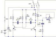
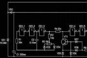
Schematic diagram of an AVR oscilloscope shown in the picture below (click to enlarge):

The supply voltage for the circuit is 12 volts DC. From this voltage, in the future, 2 more voltages are obtained: + 8.2V for IC1 and + 5V for IC2, IC3. The device can measure the input voltage from + 2.5V to -2.5V or from 0 to + 5V, depending on the position of the S1 switch (select the type of input current: DC or AC). When using a 1:10 probe, the input voltage can be increased accordingly by a factor of 10. In addition, by switch S2, you can additionally set the voltage division by 2.
ATmega32 firmware
Firmware file: AVR_oscilloscope.hex, when selecting fuses, you must specify the use of external quartz. After that, it is imperative to turn off the JTAG interface, if this is not done, the initialization screen will be displayed on the oscilloscope, and then it will go into reboot.

Customization
To configure the device, you need to do only 2 things: adjust the LCD contrast using the P2 trimmer and set the center of the waveform using the P1 trimmer.
Usage
You can move the waveform beam up or down by pressing the S8 and S4 buttons. One square on the screen corresponds to 1B.
The S7 and S3 buttons can be used to increase or decrease the measurement frequency. The minimum waveform frequency that can be displayed on the LCD is 460Hz. If you need to view a signal with a lower frequency, for example, 30Hz, then you must press S7 to compress the waveform or S3 to stretch.
The oscilloscope uses automatic trigger mode. This means that if the input signal is repetitive (eg a triangle) then the flip-flop works well. But if the waveform is constantly changing (for example, some kind of data sequence), then to fix the image, you must press the S6 button. Pressing S6 again returns to normal mode.

Oscilloscope video

List of radioelements
| Designation | Type of | Denomination | Quantity | Note | Shop | My notebook |
|---|---|---|---|---|---|---|
| IC1 | Operational amplifier | LM358 | 1 | Into notepad | ||
| IC2 | LCD display | DEM128064A | 1 | 128x64, controller KS0108 | Into notepad | |
| IC3 | MK AVR 8-bit | ATmega32 | 1 | Into notepad | ||
| IC4 | Linear regulator | LM7805 | 1 | Into notepad | ||
| D1 | Zener diode | 1N4738A | 1 | 8.2V | Into notepad | |
| D2 | Rectifier diode | 1N4007 | 1 | Into notepad | ||
| C1 | Capacitor | 470 nF | 1 | Into notepad | ||
| C2 | Capacitor | 27 pF | 1 | Into notepad | ||
| C3 | 22 μF 16 V | 1 | Into notepad | |||
| C4, C7, C9 | Capacitor | 100 nF | 3 | Into notepad | ||
| C5, C6 | Capacitor | 22 pF | 2 | Into notepad | ||
| C8 | Electrolytic capacitor | 100 μF 25 V | 1 | Into notepad | ||
| R1, R2, R4 | Resistor | 1 MOhm | 3 | Into notepad | ||
| R3, R5 | Resistor | 390 k Ohm | 2 | Into notepad | ||
| R6 | Resistor | 56 Ohm | 1 | Into notepad | ||
| R7 | Resistor | 220 ohm | 1 | Into notepad | ||
| P1 | Trimmer resistor | 10 kΩ | 1 | Into notepad | ||
| P2 | Trimmer resistor | 22 kΩ | 1 | Into notepad | ||
| X1 | Quartz | 16 MHz | 1 |
Technology does not stand still, and it is not always easy to keep up with them. There are new items that I would like to understand in more detail. This is especially true for a variety of devices that allow you to assemble almost any simple device step by step. Now among them are Arduino boards with their clones, and Chinese microprocessor computers, and ready-made solutions that come with software on board.
However, to work with all of the above range of interesting new products, as well as to repair digital equipment, an expensive high-precision tool is required. Among such equipment is an oscilloscope that allows you to read frequency readings and carry out diagnostics. The cost is often quite high, and novice experimenters cannot afford such an expensive purchase. Here a solution comes to the rescue, which appeared on many radio amateur forums almost immediately after the appearance of tablets on the Android system. Its essence is to make an oscilloscope from a tablet with minimal costs, without making any modifications or modifications to your gadget, and also eliminating the risk of damaging it.
What is an oscilloscope
The oscilloscope - as a device for measuring and tracking frequency fluctuations in an electrical network - has been known since the middle of the last century. All educational and professional laboratories are equipped with these devices, since it is possible to detect some malfunctions or fine-tune the equipment only with its help. He can display information both on the screen and on paper tape. The readings allow you to see the shape of the signal, calculate its frequency and intensity, and as a result, determine the source of its occurrence. Modern oscilloscopes allow you to draw 3D color frequency plots. Today we will focus on a simple version of a standard two-channel oscilloscope and implement it using an attachment to a smartphone or tablet and the corresponding software.
The easiest way to create a pocket oscilloscope
If the measured frequency is in the range of frequencies audible to the human ear, and the signal level does not exceed the standard microphone level, then you can assemble an oscilloscope from an Android tablet with your own hands without any additional modules. To do this, it is enough to disassemble any headset, on which a microphone must be present. If there is no suitable headset, then you will need to buy a 3.5 mm audio plug with four contacts. Before soldering the probes, check the pinout of the connector of your gadget, because there are two types of them. The probes must be connected to the pins corresponding to the microphone connection on your device.
Next, you should download software from the "Market" that can measure the frequency at the microphone input and draw a graph based on the received signal. There are quite a few such options. Therefore, if you wish, there will be plenty to choose from. As mentioned earlier, there was no need to redesign the tablet. The oscilloscope will be ready immediately after you calibrate the application.

Pros and cons of the above scheme
The advantages of such a solution can be clearly attributed to the simplicity and low cost of assembly. An old headset or one new connector costs almost nothing, and it only takes a few minutes.
But this scheme has a number of significant disadvantages, namely:
- Small range of measured frequencies (depending on the quality of the sound path of the gadget, it ranges from 30 Hz to 15 kHz).
- Lack of protection for the tablet or smartphone (if the probes are accidentally connected to sections of the circuit with increased voltage, at best, you can burn the microcircuit responsible for processing the audio signal on your gadget, and at worst, completely disable your smartphone or tablet).
- On very cheap devices, there is a significant error in signal measurement, reaching 10-15 percent. Such a figure is unacceptable for fine tuning the equipment.
Implementation of protection, signal shielding and error reduction
In order to partially protect your device from possible failure, as well as stabilize the signal and expand the range of input voltages, a simple oscilloscope circuit for a tablet can be used, which has long been successfully used to assemble devices for a computer. It uses cheap components, including KS119A zener diodes and two 10 and 100 kΩ resistors. Zener diodes and the first resistor are connected in parallel, and the second, more powerful, resistor is used at the input of the circuit to expand the maximum possible voltage range. As a result, a large amount of interference disappears, and the voltage rises to 12 V.
Of course, it should be borne in mind that the oscilloscope from the tablet works primarily with sound impulses. Therefore, it is worth taking care of high-quality shielding of both the circuit itself and the probes. If desired, detailed instructions for assembling this circuit can be found on one of the thematic forums.

Software
To work with such a scheme, you need a program that can draw graphs based on the incoming audio signal. It is not difficult to find it in the "Market", there are many options. Almost all of them involve additional calibration, so you can achieve the highest possible accuracy, and make a professional oscilloscope from a tablet. Otherwise, these programs perform essentially the same task, so the final choice depends on the required functionality and usability.
Homemade set-top box with Bluetooth-module
If a wider frequency range is required, then the above option will not work. Here a new option comes to the rescue - a separate gadget, which is a set-top box with an analog-to-digital converter that provides digital signal transmission. In this case, the audio path of a smartphone or tablet is no longer used, which means that a higher measurement accuracy can be achieved. In fact, at this stage, they are only a portable display, and all information is collected by a separate device.
You can assemble an oscilloscope from an Android tablet with a wireless module yourself. There is an example on the network when a similar device was implemented back in 2010 using a two-channel analog-to-digital converter based on the PIC33FJ16GS504 microcontroller, and the LMX9838 Bluetooth module served as a signal transmitter. The device turned out to be quite functional, but difficult to assemble, so for beginners it will be an overwhelming task to make it. But, if you wish, it is not a problem to find a similar project on the same radio amateur forums.

Ready-made set-top boxes with Bluetooth
Engineers do not sleep, and, in addition to handicrafts, more and more consoles appear in stores that perform the function of an oscilloscope and transmit a signal via a Bluetooth channel to a smartphone or tablet. An oscilloscope set-top box to a tablet connected via Bluetooth often has the following main characteristics:
- Measured frequency limit: 1MHz.
- Probe voltage: up to 10 V.
- Radius of action: about 10 m.
These characteristics are quite enough for domestic use, and yet in professional activities sometimes there are cases when this range is sorely lacking, and it is simply unrealistic to implement a larger one with a slow Bluetooth protocol. What way out can there be in this situation?
Oscilloscopes-set-top boxes with data transmission over Wi-Fi
This option of data transmission significantly expands the capabilities of the measuring device. Now the market for oscilloscopes with this type of information exchange between a set-top box and a tablet is gaining momentum due to its demand. Such oscilloscopes are practically not inferior to professional ones, since they transfer the measured information to a tablet without delay, which immediately displays it in the form of a graph on the screen.
Control is carried out through simple, intuitive menus that copy the setting elements of conventional laboratory devices. In addition, such equipment allows you to record or broadcast in real time everything that happens on the screen, which can be an indispensable help if you need to ask for advice from a more experienced master located elsewhere.
The characteristics of an oscilloscope for a set-top box with a Wi-Fi connection grow several times compared to previous options. Such oscilloscopes have a measurement range of up to 50 MHz, and they can be modified using a variety of adapters. Often, they are equipped with batteries for autonomous power supply, in order to unload the workplace as much as possible from unnecessary wires.

Homemade options for modern set-top box oscilloscopes
Of course, there is a burst of various ideas on the forums, with the help of which enthusiasts are trying to fulfill their old dream - to independently assemble an oscilloscope from an Android tablet with a Wi-Fi channel. Some models work well, others don't. It remains for you to decide whether to try your luck too and save a few dollars by assembling the device yourself, or to purchase a ready-made version. If you are not confident in your abilities, then it is better not to take risks, so that later you do not regret the wasted funds.
Otherwise - welcome to one of the communities of radio amateurs, where they can give you good advice. Perhaps, later, it is according to your scheme that beginners will assemble their first oscilloscope in their life.

Set-top box software
Often, along with purchased set-top oscilloscopes, a disc is supplied with a program that you can install on your tablet or smartphone. If there is no such disc in the kit, then carefully study the instructions for the device - most likely, it contains the names of programs compatible with the console and located in the application store.
Also, some of these devices can work not only with devices running the Android operating system, but also with more expensive Apple devices. In this case, the program will definitely be in the AppStore, since there is no other installation option. After making an oscilloscope from a tablet, do not forget to check the accuracy of the readings and, if necessary, calibrate the instrument.

USB oscilloscopes
If you don't have a portable device like a tablet, but you have a laptop or computer, don't be upset. You can also make an excellent one of them. The simplest option would be to connect the probes to the microphone input of the computer in the same way as described at the beginning of the article.
However, given its limitations, this option is not for everyone. In this case, a USB oscilloscope can be used, which will provide the same characteristics as a set-top box with signal transmission over Wi-Fi. It is worth noting that such devices sometimes work with some tablets that support the technology for connecting external OTG devices. Of course, they are also trying to make a YUSB oscilloscope on their own, and quite successfully. At least, a large number of topics on the forums are devoted to this particular craft.
It is no secret that novice radio amateurs do not always have expensive measuring equipment on hand. For example, an oscilloscope, which even in the Chinese market, the cheapest model costs about several thousand.
Sometimes an oscilloscope is needed to repair various circuits, check amplifier distortions, adjust sound equipment, etc. Very often, a low-frequency oscilloscope is used to diagnose the operation of sensors in a car.
In this case, the simplest oscilloscope made from your personal computer will help you. No, your computer does not have to be disassembled or modified in any way. You just need to solder the prefix - divider for everything, and connect it to the PC via the audio input. And to display the signal, install special software. In a couple of tens of minutes, you will have your own oscilloscope, which may well be suitable for analyzing signals. By the way, you can use not only a stationary PC, but also a laptop or netbook.
Of course, such an oscilloscope is comparable with a real device, since it has a small frequency range, but it is a very useful thing in the household to see the amplifier outputs, various ripple of power supplies, etc.
Prefix diagram
Agree that the circuit is incredibly simple and does not take a lot of time to assemble it. This is a divider-limiter that will protect your computer's sound card from dangerous voltages that you might accidentally drop into the input. The divider can be 1, 10 and 100. The sensitivity of the entire circuit is regulated by a variable resistor. The set-top box is connected to the line-in of the PC sound card.We collect the prefix
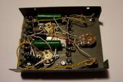
You can take a battery box like me or another plastic case.
Software
The "oscilloscope" program will visualize the signal applied to the input of the sound card. I will offer you two options for downloading:1) A simple program without installation with a Russian interface, download it.
(Downloads: 9807)

2) And the second is with the installation, you can download it -.

Which one to use is up to you. Take and install both, and then choose.
If you already have a microphone installed, then after installing and launching the program, you can already observe the sound waves that enter the microphone. It means everything is OK.
For the set-top box, no more drivers are required.
We connect the set-top box to the line or microphone input of the sound card and use it for health.

If you have never had any experience with an oscilloscope in your life, then I sincerely recommend that you repeat this homemade product and work with such a virtual instrument. The experience is very valuable and interesting.