How to connect a load to a control unit on microcircuits. Triac power regulator Circuits with to125 12 5
A selection of circuits and a description of the operation of the power regulator on triacs and not only. Triac power control circuits are well suited for extending the life of incandescent lamps and for adjusting their brightness. Or for powering non-standard equipment for example 110 volts.
The figure shows a circuit of a triac power regulator, which can be changed by changing the total number of network half-periods passed by the triac over a certain period of time. On the elements of the microcircuit DD1.1.DD1.3 is made, the oscillation period of which is about 15-25 network half-periods.

The duty cycle is controlled by resistor R3. Transistor VT1 together with diodes VD5-VD8 is designed to bind the moment the triac is turned on during the transition of the mains voltage through zero. Basically, this transistor is open, respectively, the DD1.4 input receives "1" and the VT2 transistor with the VS1 triac are closed. At the moment of crossing zero, the transistor VT1 closes and opens almost immediately. Moreover, if the DD1.3 output was 1, then the state of the DD1.1.DD1.6 elements will not change, and if the DD1.3 output was "zero", then the DD1.4.DD1.6 elements will generate a short pulse, which will be amplified by transistor VT2 and open the triac.
As long as the output of the generator is a logical zero, the process will cycle the disc after each transition of the mains voltage through the zero point.


The basis of the circuit is a foreign triac mac97a8, which allows switching high power connected loads, and used an old Soviet variable resistor to adjust it, and used a regular LED as an indication.
The triac power regulator uses the principle of phase control. The operation of the power regulator circuit is based on a change in the moment the triac is turned on relative to the transition of the mains voltage through zero. At the initial moment of the positive half-cycle, the triac is in the closed state. With increasing mains voltage, the capacitor C1 is charged through the divider.

The increasing voltage across the capacitor is phase shifted from the mains by an amount that depends on the total resistance of both resistors and the capacitance of the capacitor. The capacitor is charged until the voltage across it reaches the "breakdown" level of the dinistor, approximately 32 V.
At the moment the dinistor opens, the triac will also open, a current will flow through the load connected to the output, depending on the total resistance of the open triac and the load. The triac will be open until the end of the half cycle. Resistor VR1 sets the opening voltage of the dinistor and triac, thereby regulating the power. At the moment of the negative half-period, the algorithm of the circuit is similar.
A variant of the scheme with minor modifications for 3.5 kW
The regulator circuit is simple, the load power at the output of the device is 3.5 kW. With this HAM DIY you can control lighting, heating elements and much more. The only significant drawback of this circuit is that it is impossible to connect an inductive load to it in any case, because the triac will burn out!

Radio components used in the construction: Triac T1 - BTB16-600BW or similar (KU 208 il VTA, VT). Dinistor T - type DB3 or DB4. 0.1μF ceramic capacitor.
Resistance R2 510 Ohm limits the maximum volts on the capacitor to 0.1 μF, if you put the regulator slider in the 0 Ohm position, then the circuit resistance will be about 510 Ohm. The capacitance is charged, through resistors R2 510 Ohm and variable resistance R1 420 kOhm, after U on the capacitor reaches the opening level of the DB3 dinistor, the latter will form a pulse that unlocks the triac, after which, with further passage of the sinusoid, the triac is locked. The opening-closing frequency of T1 depends on the level U on the 0.1uF capacitor, which depends on the resistance of the variable resistor. That is, by interrupting the current (with a high frequency) the circuit, thereby regulating the output power.
For each positive half-wave of the input alternating voltage, the capacitance C1 is charged through the chain of resistors R3, R4, when the voltage across the capacitor C1 becomes equal to the opening voltage of the VD7 dinistor, its breakdown occurs and the capacitance is discharged through the diode bridge VD1-VD4, as well as the resistance R1 and the control electrode VS1. To open the triac, an electrical circuit of diodes VD5, VD6 of capacitor C2 and resistance R5 is used.

It is required to select the value of the resistor R2 so that with both half-waves of the mains voltage, the triac of the regulator reliably works, and it is also required to select the values of the resistances R3 and R4 so that when the handle of the variable resistance R4 is rotated, the voltage across the load smoothly changes from minimum to maximum values. Instead of the TC 2-80 triac, you can use the TC2-50 or TC2-25, although there will be a small loss in terms of the permissible power in the load.

KU208G, TS106-10-4, TS 112-10-4 and their analogs were used as a triac. At that moment in time when the triac is closed, the capacitor C1 is charged through the connected load and resistors R1 and R2. The charge rate is changed by the resistor R2, the resistor R1 is designed to limit the maximum value of the charge current
When the threshold voltage value is reached on the capacitor plates, the key is opened, the capacitor C1 is quickly discharged to the control electrode and switches the triac from the closed state to the open, in the open state the triac shunts the circuit R1, R2, C1. At the moment the mains voltage crosses zero, the triac closes, then the capacitor C1 is charged again, but with a negative voltage.
Capacitor C1 from 0.1 ... 1.0 μF. Resistor R2 1.0 ... 0.1 MΩ. The triac is switched on by a positive current pulse to the control electrode at a positive voltage at the terminal of the conventional anode and a negative current pulse to the control electrode at a negative voltage of the conventional cathode. Thus, the key element for the regulator must be bi-directional. You can use a bidirectional dinistor as a key.
Diodes D5-D6 are used to protect the thyristor from possible reverse voltage breakdown. The transistor operates in avalanche breakdown mode. Its breakdown voltage is about 18-25 volts. If you do not find P416B, then you can try to find a replacement for it.

The pulse transformer is wound on a ferrite ring with a diameter of 15 mm, grade H2000. The thyristor can be replaced with KU201
The circuit of this power regulator is similar to the above circuits, only the interference suppression circuit C2, R3 is introduced, and the SW switch makes it possible to break the charging circuit of the control capacitor, which leads to instant locking of the triac and disconnection of the load.

C1, C2 - 0.1 MKF, R1-4k7, R2-2 mOhm, R3-220 Ohm, VR1-500 kOhm, DB3 - dinistor, BTA26-600B - triac, 1N4148 / 16 V - diode, any LED.
The regulator is used to adjust the load power in circuits up to 2000 W, incandescent lamps, heating devices, a soldering iron, asynchronous motors, a car charger, and if you replace the triac with a more powerful one, it can be used in the current control circuit in welding transformers.

The principle of operation of this power regulator circuit is that a half-cycle of the mains voltage is supplied to the load after a selected number of missing half-periods.

The diode bridge rectifies the AC voltage. Resistor R1 and Zener diode VD2, together with the filter capacitor, form a 10 V power supply to power the K561IE8 microcircuit and the KT315 transistor. The rectified positive half-periods of the voltage passing through the capacitor C1 are stabilized by the Zener diode VD3 at a level of 10 V. Thus, pulses with a frequency of 100 Hz follow to the counting input C of the K561IE8 counter. If the switch SA1 is connected to output 2, then the level of a logical unit will be constantly present at the base of the transistor. Because the pulse to zero the microcircuit is very short and the counter has time to restart from the same pulse.
At pin 3, the level of a logical unit will be set. The thyristor will be open. All power will be allocated to the load. In all subsequent positions of SA1 at pin 3 of the counter, one pulse will pass through 2-9 pulses.
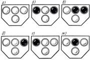
The K561IE8 microcircuit is a decimal counter with a positional decoder at the output, so the level of a logical unit will be periodically at all outputs. However, if the switch is set to output 5 (pin 1), then the counting will occur only up to 5. When the pulse passes through output 5, the microcircuit will reset to zero. The counting will start from zero, and on pin 3 the level of a logical unit will appear for the duration of one half-period. At this time, the transistor and thyristor open, one half-cycle passes into the load. In order to make it clearer, I present the vector diagrams of the circuit's operation.

If you need to reduce the load power, you can add another counter chip by connecting pin 12 of the previous chip to pin 14 of the next one. By installing another switch, it will be possible to adjust the power up to 99 missed pulses. Those. you can get about a hundredth of the total power.
The KR1182PM1 microcircuit has in its internal composition two thyristors and a control unit for them. The maximum input voltage of the KR1182PM1 microcircuit is about 270 Volts, and the maximum load can reach 150 W without using an external triac and up to 2000 W with the use, and also taking into account that the triac will be installed on the radiator.

To reduce the level of external noise, capacitor C1 and choke L1 are used, and capacitance C4 is required to smoothly switch on the load. The regulation is carried out using the resistance R3.
A selection of fairly simple regulator circuits for a soldering iron will simplify the life of a radio amateur
The combination consists in combining the convenience of using a digital controller and the flexibility of simple adjustment.

The considered circuit of the power regulator works on the principle of changing the number of periods of the input AC voltage going to the load. This means that the device cannot be used to adjust the brightness of incandescent lamps due to the flickering visible to the eye. The circuit makes it possible to adjust the power within eight preset values.
There is a huge number of classic thyristor and triac regulator circuits, but this regulator is made on a modern element base and, in addition, was a phase one, i.e. does not pass the entire half-wave of the mains voltage, but only some of it, thereby limiting the power, because the triac opens only at the desired phase angle.
The device shown in Fig. 1 is designed for modulating control in low-power loads. With its help, it is possible to power the second additional radio engineering device from one power source, which has a supply of power. For example, a 15 ... 20 V power supply supplies the necessary circuit, and you need to additionally power a transistor receiver from it, which has a supply voltage lower (3 ... 9 V). Scheme made on a field-effect epitaxial-planar transistor with a p-n-junction and an n-channel KP903. During the operation of the device, the property of the current-voltage characteristics of this transistor was used at different voltages between the gate and the source. The family of characteristics KP903A ... B is given in. The input supply voltage of this device is 15 ... 20 V. Resistor R2 of the PPB-ZA type with a nominal value of 150 Ohm. It can be used to set the required voltage in the load. Disadvantage regulator is the rise in the internal resistance of the device when the operating voltage decreases. T160 current regulator diagram Fig. 2 shows scheme indicator stresses the above-described regulator, assembled on a field-effect transistor KP103. The device is designed to control stresses in load. Connecting this indicator to the device regulator is carried out according to the above diagram. Depending on the letter index KP103 of the indicator installed in the circuit (Fig. 2), we will fix (at the moment of ignition of the HL1 LED with an increase in the output voltage) the operating voltage in the load. The effect of fixing different voltages in the load is obtained as a result of the fact that the channel transistors KP103 have different stresses cutoffs depending on the letter index, for example, for the KP103E transistor, this is 0.4-1.5 V, for the KP103Zh - 0.5-2.2 V, for the KP103I - 0.8-3 V, etc. By installing the transistor ...
For the scheme "Simple power regulator"
The load of this simple power can include incandescent lamps, heating devices of various types, etc., corresponding to the power used by the thyristors. The regulator tuning technique is contained in the selection of a variable regulating resistor. However, it is best to select a potentiometer in series with a fixed resistor so that the voltage at the power output varies as widely as possible. A. ANDRIENKO, Kostroma ...
For the scheme "Universal low voltage power supply"
In practice, very often, to power various devices, from 3 to 12 V are required. The described power supply unit allows obtaining the following row: 3; 4.5 (5); nine; 12 V at load current up to 300 mA. There is a possibility of promptly changing the polarity of the output voltage. ...
For the "VOLTAGE CONVERTER" circuit
CONVERTER S. Sych225876, Brest region, Kobrin district, Orekhovsky village, Lenin st., 17 - 1. I offer a simple and reliable converter circuit stresses for the management of varicaps in various designs, which generates 20 V when powered from 9 V. A variant of the converter with a voltage multiplier was chosen, since it is considered the most economical. In addition, it does not interfere with radio reception. A pulse generator close to rectangular is assembled on transistors VT1 and VT2. A voltage multiplier is assembled on diodes - VD1 ... VD4 and capacitors C2 ... C5. Resistor R5 and zener diodes VD5, VD6 form a parametric voltage regulator. The output capacitor C6 is a high-pass filter. The current consumption of the converter depends on stresses nutrition and the number of varicaps, as well as their type. It is desirable to enclose the device in a shield to reduce interference from the generator. A properly assembled device works immediately and is uncritical to the ratings of the parts ...
For the diagram "Voltage converter 5 -> 230V"
Power supply Converter 5 -> 230 V Chips: DD1 - K155LA3 DD2 - K1554TM2 Transistors: VT1 - VT3 - KT698G, VT2 - VT4 - KT827B, VT5- KT863А Resistors: R1 - 910, R2 - 1k, R320 - 1k, R4t - 120 0.25 W, R6 - 500 0.25 W, R7 - R8 - 56 Ohm 2W, R9 - 1.5 kOm2W Diode VD5 - KC620A two-in-series Capacitors: C1 - 10H5 C2 - 22 μF x450V Transformer: T1 - two windings of 10 volts connected, one 16A winding; for 220 volts current 1A, frequency 25kHz = Converter stresses 5 - 230V ...
For the diagram "Repair of charger for MPEG4-player"
After two months of operation, the "nameless" charger for a pocket MPEG4 / MP3 / WMA player failed. Of course, there was no scheme for it, so I had to draw it up on the circuit board. The numbering of active elements on it (Fig. 1) is conditional, the rest correspond to the inscriptions on the printed circuit board. stresses implemented on a low-power high-voltage transistor VT1 of the type MJE13001, the unit for stabilizing the output stresses produced on transistor VT2 and optocoupler VU1. In addition, the transistor VT2 protects VT1 from overload. Transistor VT3 is designed to indicate the end of battery charging. Upon examination of the product, it turned out that the transistor VT1 "went to a break", and VT2 was broken. Resistor R1 also burned out. It took no more than 15 minutes to troubleshoot. But with proper repair of any radio-electronic product, it is usually not enough to eliminate malfunctions alone, you still need to find out the reasons for their occurrence so that this does not happen again. The radio microphone of the circuit As it turned out, during the operating hour of the charger, moreover, with the load disconnected and the case open, the VT1 transistor, made in the TO-92 case, warmed up to a temperature of approximately 90 ° C. Since there were no more powerful transistors nearby that could replace the MJE13001, I decided to glue a small heat sink to it. Photo of the charger is shown in Fig. 2. A duralumin heatsink with dimensions 37x15x1 mm is glued to the transistor body with "Radial" body-conducting glue. The same glue can also be used to glue the heatsink to the circuit board. With the heat sink, the temperature of the transistor case dropped to 45 ... 50 ° C. The reason for the initially strong heating of the transistor VT1. perhaps, lies in the "simplification" in the assembly of its damper circuit. The design and topology of the printed circuit board suggest that in ...
For the diagram "Power regulator on three parts"
Recently, resistor and transistor power regulators are experiencing a real renaissance. They are the most uneconomical. You can increase the efficiency in the same way as by turning on a diode (see figure). This achieves a more convenient regulation limit (50-100%). Semiconductors can be placed on a single heat sink. Yu.I. Borodaty, Ivano-Frankivsk region Literature 1. Danilchuk A.A. Power regulator for a soldering iron / / Radioamator-Electric. -2000. -№9. -P.23. 2.Rishtun A Tightness regulator on six parts // Radioamator-Electric. -2000. -№11. -S. 15 ....
For the diagram "Converter of DC voltage 12 V to AC 220 V"
12V-AC 220V converter Anton Stoilov Offered scheme constant converter stresses 12V AC 220V, which, when connected to a 44 Ah car battery, can supply a 100-watt load for 2-3 hours. It consists of a master oscillator on a symmetric multivibrator VT1, VT2, loaded on powerful paraphase switches VT3-VT8, switching the current in the primary winding of the step-up transformer TV. VD3 and VD4 protect powerful transistors VT7 and VT8 from overvoltage during no-load operation. The transformer is made on a magnetic circuit Ш36х36, the windings W1 and W1 "have 28 turns of PEL 2.1, and W2 - 600 turns of PEL 0.59, and W2 is first wound, and on top of it with a double wire (with the task of achieving the symmetry of the semi-windings) W1. When adjusting with the RP1 trimmer, minimal distortion of the output shape is achieved. stresses"Radio Television Electronics" N6 / 98, p. 12.13 ....
For the diagram "LED voltage indicator"
In the practice of a radio amateur, a situation often arises when it is necessary to track the readings of one or another parameter. I propose a diagram of an indicator LED "ruler". Depending on the input, more or less LEDs are lit, arranged in a line (one after the other). stresses- 4 ... 12V, i.e. with an input voltage of 4 V, only one (first) LED will be lit, and with an input voltage of 4 V, the entire line will be lit. The possibilities of the circuit can be easily expanded. To monitor the alternating voltage, it is enough to install a diode bridge of low-power diodes before resistor R1. The supply voltage can be varied from 5 to 15 V by selecting the resistors R2 ... R8, respectively. The brightness of the LEDs mainly depends on the power supply of the circuit, while the input characteristics of the circuit remain practically unchanged. In order for the brightness of the LEDs to be the same, the resistors should be selected as follows: where Ik max is the collector current VT1, mA; R3 = 2R2; R4 = 3R2; R5 = 4R2; R6 = 5R2; R7 = 6R2; R8 = 7R2. Thus, when using the KT312A transistor (lK max = 30 mA) R2 = 33 Ohm. Resistor R1 enters the divider stresses and regulates the operating mode of the transistor VT1. Diodes VD1 ... VD7 can be changed to KD103A, KD105, D220, LEDs HL1 ... HL8 - to AL102. Resistor R9 limits the base current of the transistor VT1 and prevents the latter from failing when a high voltage enters the input of the circuit. A. KASHKAROV, St. Petersburg ....
For the scheme "Universal voltage regulator and charger-starting device for"
Quite often in amateur radio practice, it becomes necessary to adjust the variable in the range of 0 ... 220 V. LATRs (autotransformers) are widely used for this purpose. But their age has already passed and these bulky devices have been replaced by modern thyristor regulators, which have one drawback: the voltage in such devices is regulated by changing the duration of alternating voltage pulses. Because of this, it is impossible to connect a highly inductive load to them (for example, a transformer or a choke, as well as any other radio device containing the above elements). The voltage regulator shown in the figure is free from this drawback. It combines: overcurrent protection device, thyristor regulator stresses with bridge regulator, high efficiency (92 ... 98%). In addition, the regulator pA simple thermostat on the triac works in conjunction with a powerful transformer and rectifier, which can be used to charge car batteries and as a starting device when the battery is discharged. regulator voltage: Rated supply voltage, V 220 ± 10%; Output voltage of alternating current, V 0 ... 215; Efficiency, not less than percentage (s) 92; Maximum load power, kW 2. Main parameters of the charger and starting device: DC output voltage, V 0 ... 40; Constant current consumed by the load, A 0 ... 20; Starting current (with starting duration 10 s), A 100 ...
The thyristor charging unit by Krasimir Rilchev is designed to charge the batteries of trucks and tractors. It provides a continuously adjustable (RP1 resistor) charging current up to 30 A. The principle of regulation is a phase-pulse based thyristor, which provides maximum efficiency, minimum power dissipation and does not require rectifier diodes. The mains transformer is made on a magnetic circuit with a cross section of 40 cm2, the primary winding contains 280 turns of PEL-1.6, the secondary 2x28 turns of PEL-3.0. Thyristors are installed on 120x120 mm heatsinks. ...
For the diagram "Thyristor relay of direction indicator"
Automotive electronics Kazan A. STAKHOV A non-contact relay for signaling vehicle turns can be designed using silicon controlled diodes - thyristors. The diagram of such a relay is shown in the figure. The relay is a conventional multivibrator on transistors T1 and T2; the switching frequency of which determines the frequency of flashing of the lamps, since the same multivibrator controls a DC switch on thyristors D1 and D4. Any low-power low-frequency transistors can work in a multivibrator. When the front and rear sidelights signal lamps are connected by the P1 switch, the multivibrator signal opens the D1 thyristor and the battery voltage is applied to the signal lamps. In this case, the right plate of the capacitor C1 is charged positively (relative to the left plate) through the resistor R5. When the triggering pulse of the multivibrator is applied to thyristor D4, the same thyristor opens and the charged capacitor C1 is connected to thyristor D1 so that it instantly receives a reverse voltage between the anode and cathode. How to check the k174ps1 microcircuit This reverse voltage closes the thyristor D1, which interrupts the current in the load. The next triggering pulse of the multivibrator opens the thyristor D1 again and the whole process repeats. Diodes D223 are used to limit negative current surges and improve thyristor starting. Any low-power thyristors with any letter indices can be used in a DC switch. When using KU201A, the current consumed by signal lamps should not exceed 2 A; for KU202A, it can reach up to 10 A. The relay can also operate from the on-board network with a voltage of 6 V. RADIO N10 1969 34 ...
For the scheme "POWER AMPLIFIER FOR MW RADIO STATION"
HF power amplifiers POWER AMPLIFIER FOR MW RADIO STATION A. SUIT (EU2001), Minsk When making a power amplifier, the question arises for radio amateurs - which active component to use in it. The advent of transistors led to the creation of a large number of designs on them. However, designing on such an element base at home is problematic for most radio amateurs. in the output stages of powerful modern metal-glass or metal-ceramic lamps such as GU-74B, etc. difficult because of their high cost. The output is widely used lamps, for example 6P45S, used in color TVs. The idea of the proposed amplifier is not new, and was described in [I]. A simple current regulator It is made on two 6P45S beam tetrodes, connected according to a scheme with grounded grids. Technical characteristics: Power gain - 8 Maximum anode current - 800 mA Anode voltage - 600 Equivalent amplifier resistance - 500 ohm Switching to transmission occurs by supplying a control voltage on relay Kl, K2. In the absence of such a voltage in the CB station, an electronic receive / transmit key can be made, as is done in. Details and design Chokes LI, L5 have an inductance of 200 µH and must be rated for a current of 800 mA. The choke L6, L7 is wound on a ring 50 VCh-2 K32x20x6 with two MGShV wires with a cross section of 1 mm2. Coils L2, L3 each contain 3 turns and are wound with a wire 0 1 mm on Rl, R2, respectively. The L4 U-loop coil is wound with a wire with a diameter of 2.5 mm. The amplifier capacitors are of the KSO type for an operating voltage of 500 V. For forced ...
For the scheme "TURNING ON POWERFUL SEMI-ELEMENT LED INDICATORS"
For the diagram "Push-pull converters (simplified calculation)"
Two-stroke converters (simplified calculation) A. PETROV, 212029, Mogilev, Schmidt Ave., 32 - 17. the occurrence of through currents, special measures must be taken to balance the hysteresis loop, or, in the simplest version, Puc. 1 - to introduce an air gap and a capacitor in series with the primary winding of the transformer. organization in converters of natural electromagnetic processes, in which the switching of keys occurs at currents equal to or close to zero. In this case, the spectrum of the current decays faster and the power of radio interference is significantly attenuated, which simplifies the filtering of both the input and output voltages. Let us dwell on the simplest half-bridge autogenerator unregulated inverter with a commutating saturable transformer (Fig. 2). Triac ts112 and circuits on it. Its advantages include the absence of a constant current component in the primary winding of the power transformer due to a capacitive divider. Fig. 2 The half-bridge circuit provides power conversion of 0.25 ... 0.5 kW in one cell. The voltages across the closed transistors do not exceed the supply voltage. The inverter has two PIC circuits: - one - by current (proportional-current control); - the second - by voltage. proportionally ...
For the diagram "Using an integrated timer for automatic voltage control"
For the diagram "Power amplifier made on a bridge circuit."
AUDIO technology A bridge power amplifier with an output power of 60 W with a single + 40 V power supply. powerful transistors are still quite small. One of the ways to increase the output power is the series-parallel connection of the same type of transistors, but this complicates the design of the amplifier and its tuning. Meanwhile, there is a way to increase the output power to avoid application hard-to-reach elements and do not increase the voltage of the power supply. This method consists in the use of two identical power amplifiers, connected in such a way that the input signal is fed to their inputs in antiphase, and the load is connected directly between the outputs of the amplifiers (a bridge circuit for switching amplifiers). VHF circuit A power amplifier made according to such a bridge circuit has the following main technical characteristics: Rated output power ....... 60 W Harmonic distortion .......... 0.5% Operating frequency band .. ........ 10 ... 25,000 Hz Supply voltage ........... 40 V Quiescent current .......... 50 mA A schematic diagram of such an amplifier is shown in Fig. .1. Changing the phase of the input signal is achieved by feeding it to the inverting input of one amplifier and to the non-inverting input of another amplifier. The load is connected directly between the outputs of the amplifiers. To provide temperature stabilization of the quiescent current of the output transistors, diodes VD1-VD4 are placed on a common heat sink with them. Fig. 1 Before switching on, check the correct installation and connections of the amplifier. After connecting the power source with a resistor R14, set a voltage between the outputs of the amplifier no more than ...
For the diagram "Simple current regulator of the welding transformer"
An important design feature of any welding machine is the possibility of adjusting the operating current. In industrial devices, different methods of adjusting the current are used: shunting with the help of chokes of all kinds, changing the magnetic flux due to the mobility of the windings or magnetic shunting, active ballast resistors and rheostats. The disadvantages of such an adjustment include the complexity of the design, the bulkiness of the resistances, their strong heating during operation, and the inconvenience when switching. The most optimal option is to make it with taps even when winding the secondary winding and, by switching the number of turns, change the current. However, this method can be used to adjust the current, but not to adjust it over a wide range. In addition, the regulation of the current in the secondary circuit of the welding transformer is associated with certain problems. So, significant currents pass through the regulating device, which leads to its bulkiness, and for the secondary circuit it is almost impossible to select such powerful standard switches so that they can withstand a current of up to 200 A. five times less. After a long search, through trial and error, the optimal solution to the problem was found - the vastly popular thyristor regulator, the circuit of which is shown in Fig. 1. With the utmost simplicity and accessibility of the element base, it is simple in management, does not require settings and has proven itself well in work - it works only as a "watch". Power regulation occurs when the primary winding of the welding transformer is periodically disconnected for a fixed period of time at each half-period of the current (Fig. 2). In this case, the average role of the current decreases. The main elements of the regulator (thyristors) are connected opposite and parallel to each other. They are alternately open ...
For the diagram "Application of tunnel diodes"
To the radio amateur designer of tunnel diodes Fig. Figures 1, 2 and 3 show three different circuit applications of a tunnel diode generator. The FM transmitter shown in Fig. 1 is very simple and provides reliable reception within a radius of 10-30 m using a whip antenna and an FM receiver of medium sensitivity. Due to the fact that the modulation scheme of the transmitter is the simplest, the output signal is somewhat distorted, and, in addition to frequency modulation, obtained by changing the oscillator's own frequency synchronously with the microphone signal, there is significant amplitude modulation. It is impossible to greatly increase the output power of such a transmitter, since it is a source of interference. Such a transmitter can be used as a portable radio microphone, a ringer or intercom for short distances. 1. The simplest tunnel diode transmitter. Radio amateur converter circuits Coil L contains 10 turns of wire PEL 0.2. The principle of operation of the local oscillator (Fig. 2) is the same as the previous transmitter. Its distinctive feature is the incomplete inclusion of the contour. It is manufactured with the goal of improving the shape and stability of the generated vibrations. A perfect sine wave can be obtained when in practice small harmonic distortion is unavoidable. 2. Tunnel diode heterodyne L = 200 μH, shown in Fig. 3 tuning fork sound frequency generator can be used as a reference for tuning musical instruments or a telegraph buzzer. The generator can also operate on diodes with lower maximum currents. In this case, the number of turns in the coils must be increased, and the dynamic loudspeaker must be switched on through the amplifier. For normal operation of the generator, the impedance is ...
For the circuit "TRANSISTOR-LAMP AM TRANSMITTER"
Radio transmitters, radio stations TRANSISTOR-LAMP AM TRANSMITTER Nowadays, portable HF and VHF radio stations are widely used. For greater efficiency, reduction in weight and dimensions, transistors are widely used in them. In this case, for a more or less radio station, circuits are used that use a generator radio tube in the output stage of the transmitter. The anode voltage for it usually comes from a voltage converter. These schemes are complex and not economical enough. The proposed scheme has increased efficiency and simplicity of design. It uses a powerful modulator and rectifier as an anode voltage source (see figure). The modulation transformer has two step-up windings - modulation and supply. The voltage taken from the supply winding is rectified and fed through the modulation winding to the anode of the output stage operating in the anode-screen modulation mode. Phase-pulse power regulator for kmop The modulator operates in B mode and has a high efficiency (up to 70%). Since the anode voltage is proportional to the modulation voltage, this circuit carries out modulation with a controlled carrier (CLC), which significantly increases efficiency. / Img / tr-la-p1.gif , 7 MHz) and gives an excitation voltage of approximately 25-30 V. It should be noted that the T1 transistor operates at a slightly increased collector voltage, so a special selection of workable copies may be required. The DR1 choke is wound on a VS-2 resistor with the conductive layer removed and has 250 turns of PEL 0.2 wire. Coils L1 and L2 each contain 12 turns of PEL 1.2 wire. The diameter of the coils is 12 mm, the length of the winding is 20 mm. Taps in cat ...
The article describes how a thyristor power regulator works, the circuit of which will be presented below.
In everyday life, it is very often necessary to regulate the power of household appliances, for example, an electric stove, a soldering iron, boilers and heating elements, in transport - engine speed, etc. The simplest radio amateur design comes to the rescue - a power regulator on a thyristor. It is not difficult to assemble such a device, it can become the very first home-made device that will perform the function of adjusting the temperature of the soldering iron tip of a novice radio amateur. It should be noted that ready-made soldering stations with temperature control and other pleasant functions are much more expensive than a simple soldering iron. The minimum set of parts allows you to assemble a simple wall-mounted thyristor power regulator.
For your information, surface mounting is a way of assembling electronic components without using a printed circuit board, and with good skill, it allows you to quickly assemble electronic devices of average complexity.
You can also order a thyristor regulator, and for those who want to figure it out on their own, a diagram will be presented below and the principle of operation will be explained.
Incidentally, this is a single-phase thyristor power regulator. Such a device can be used to control power or the number of revolutions. However, first you need to understand, because this will allow us to understand for what load it is better to use such a regulator.
How does a thyristor work?
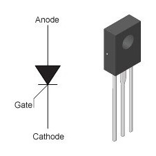
A thyristor is a controlled semiconductor device capable of conducting current in one direction. The word "controlled" is used for a reason, because with its help, unlike a diode, which also conducts current to only one pole, it is possible to choose the moment when the thyristor begins to conduct current. The thyristor has three outputs:
- Anode.
- Cathode.
- Control electrode.
In order for the current to start flowing through the thyristor, the following conditions must be met: the part must be in a live circuit, and a short pulse must be applied to the control electrode. Unlike a transistor, thyristor control does not require holding the control signal. This is not the end of the nuances: the thyristor can be closed by only interrupting the current in the circuit, or by forming a reverse anode-cathode voltage. This means that the use of a thyristor in DC circuits is very specific and often unreasonable, but in AC circuits, for example, in such a device as a thyristor power regulator, the circuit is built in such a way that a condition for closing is provided. Each of the half-waves will close the corresponding thyristor.
You, most likely, do not understand everything? Do not despair - the process of the finished device will be described in detail below.
Scope of thyristor regulators
In what circuits is it effective to use a thyristor power regulator? The circuit allows you to perfectly regulate the power of heating devices, that is, to affect the active load. When working with a highly inductive load, the thyristors may simply not close, which can lead to the failure of the regulator.
Can you motor?
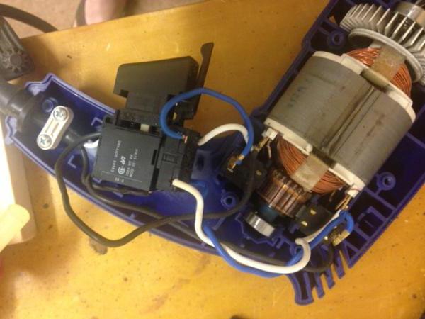
I think many of the readers have seen or used drills, angle grinders, which are popularly called "grinders", and other power tools. You may have noticed that the number of turns depends on the depth of pressing the trigger of the device. It is in this element that such a thyristor power regulator is built (the diagram of which is shown below), with the help of which the number of revolutions is changed.
Note! The thyristor regulator cannot change the speed of asynchronous motors. Thus, the voltage is regulated on brushed motors equipped with a brush assembly.
Scheme of one and two thyristors
A typical circuit for assembling a thyristor power regulator with your own hands is shown in the figure below.

The output voltage of this circuit is from 15 to 215 volts, in the case of using these thyristors installed on heat sinks, the power is about 1 kW. By the way, a switch with a dimmer is made according to a similar scheme.
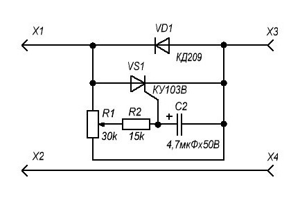
If you do not need full voltage regulation and you only need to get 110 to 220 volts at the output, use this diagram, which shows a half-wave power regulator on a thyristor.
How it works?

The information described below is valid for most circuits. The letter designations will be taken in accordance with the first circuit of the thyristor regulator
The thyristor power regulator, the principle of operation of which is based on phase control of the voltage value, also changes the power. This principle is that, under normal conditions, the load is acted upon by an alternating voltage of the household network, which changes according to a sinusoidal law. Above, when describing the principle of operation of a thyristor, it was said that each thyristor works in one direction, that is, it controls its half-wave from a sinusoid. What does it mean?
If, with the help of a thyristor, the load is periodically connected at a strictly defined moment, the value of the effective voltage will be lower, since part of the voltage (the effective value that "gets" to the load) will be less than the mains voltage. This phenomenon is illustrated in the graph.
The shaded area is the area of stress that is under load. The letter "a" on the horizontal axis indicates the moment when the thyristor opens. When the positive half-wave ends and a period with a negative half-wave begins, one of the thyristors closes, and at the same moment the second thyristor opens.
Let's figure out how our thyristor power regulator works specifically
The first scheme
Let us stipulate in advance that instead of the words "positive" and "negative", "first" and "second" (half-wave) will be used.
So, when the first half-wave begins to act on our circuit, the capacities C1 and C2 begin to charge. Their charge rate is limited by potentiometer R5. this element is variable, and with its help the output voltage is set. When the voltage required to open the dynistor VS3 appears on the capacitor C1, the dynistor opens, a current flows through it, with the help of which the thyristor VS1 will be opened. The moment of breakdown of the dinistor is point "a" on the chart presented in the previous section of the article. When the voltage value crosses zero and the circuit is under the second half-wave, the thyristor VS1 closes, and the process is repeated again, only for the second dynistor, thyristor and capacitor. Resistors R3 and R3 are used for control, and R1 and R2 are used for thermal stabilization of the circuit.
The principle of operation of the second circuit is similar, but it controls only one of the half-waves of the alternating voltage. Now, knowing the principle of operation and the circuit, you can assemble or repair a thyristor power regulator with your own hands.
The use of the regulator in everyday life and safety

It must be said that this circuit does not provide galvanic isolation from the network, therefore there is a danger of electric shock. This means that you should not touch the regulator elements with your hands. An insulated enclosure must be used. The design of your device should be designed so that, if possible, you can hide it in an adjustable device, find free space in the case. If the adjustable device is stationary, then in general it makes sense to connect it through a switch with a dimmer. Such a solution will partially protect against electric shock, eliminate the need to search for a suitable case, has an attractive appearance and is manufactured using an industrial method.
An article about various ways to connect a load to a microcontroller control unit using relays and thyristors.
All modern equipment, both industrial and domestic, is powered by electricity. Moreover, its entire electrical circuit can be divided into two large parts: control devices (controllers from the English word CONTROL - to control) and actuators.
About twenty years ago, control units were executed on microcircuits of a small and medium degree of integration. These were the series of microcircuits K155, K561, K133, K176 and the like. They are called because they perform logical operations on signals, and the signals themselves are digital (discrete).
Exactly the same as usual contacts: "closed - open". Only in this case are these states called "logical one" and "logical zero", respectively. The voltage of a logical unit at the output of microcircuits is in the range from half of the supply voltage to its full value, and the voltage of a logical zero for such microcircuits, as a rule, is 0 ... 0.4V.
The algorithm of operation of such control units was carried out due to the appropriate connection of microcircuits, and their number was quite large.
Currently, all control units are developed on the basis of. In this case, the algorithm of operation is laid not by the circuit connection of individual elements, but by the program "stitched" in the microcontroller.
In this regard, instead of several tens or even hundreds of microcircuits, the control unit contains a microcontroller and a number of microcircuits for interacting with the "outside world". But, despite this improvement, the signals of the microcontroller control unit are still the same digital ones as in the old microcircuits.
It is clear that the power of such signals is not enough to turn on a powerful lamp, an engine, and just a relay. In this article, we will look at in what ways can powerful loads be connected to microcircuits.
Most. In Figure 1, the relay is turned on using a transistor VT1, for this, a logical unit is fed to its base through the resistor R1 from the microcircuit, the transistor opens and turns on the relay, which, with its contacts (not shown in the figure), turns on the load.

The cascade shown in Figure 2 works differently: to turn on the relay at the output of the microcircuit, a logical 0 must appear, which will close the transistor VT3. in this case, the VT4 transistor will open and turn on the relay. The SB3 button can be used to manually turn on the relay.

In both figures, you can see that diodes are connected in parallel to the relay windings, and with respect to the supply voltage in the opposite (non-conductive) direction. Their purpose is to extinguish the EMF of self-induction (it can be ten or more times higher than the supply voltage) when the relay is turned off and to protect the circuit elements.
If in the circuit there are not one, two relays, but much more, then for their connection a specialized microcircuit ULN2003A allowing connection of up to seven relays. Such a switching circuit is shown in Figure 3, and in Figure 4 the appearance of a modern small-sized relay.


Figure 5 shows (instead of which, without changing anything in the circuit, you can connect a relay). In this diagram, you should pay attention to the transistor switch, made on two transistors VT3, VT4. A similar complication is caused by the fact that some microcontrollers, for example AT89C51, AT89C2051, hold logic 1 on all pins for several milliseconds for a few milliseconds during the power-on reset. which can be very undesirable.
In order to turn on the load (in this case, the LEDs of the optocoupler thyristors V1, V2), a logical 0 should be applied to the base of the transistor VT3 through the resistor R12, which will lead to the opening of VT3 and VT4. The latter will light the LEDs of the optical thyristors, which will open and turn on the mains load. Optocoupler thyristors provide galvanic isolation from the network of the control circuit itself, which increases the electrical safety and reliability of the circuit.
A few words about thyristors. Without going into technical details and current-voltage characteristics, we can say that it is a simple diode, they even have similar designations. But the thyristor also has a control electrode. If a positive pulse is applied to it with respect to the cathode, even a short one, the thyristor will open.
The thyristor will be in the open state as long as current flows through it in the forward direction. This current must be at least a certain amount, called the holding current. Otherwise, the thyristor simply will not turn on. You can turn off the thyristor only by breaking the circuit or applying a voltage of reverse polarity. Therefore, in order to pass both half-waves of the alternating voltage, an anti-parallel connection of two thyristors is used (see Fig. 5).
In order not to make such an inclusion, triacs are produced either in the bourgeois language. They already have two thyristors in the same case, connected in opposite directions - in parallel. They have a common control electrode.
Figure 6 shows the appearance and pinout of thyristors, and Figure 7 shows the same for triacs.


Figure 8 shows circuit for connecting a triac to a microcontroller (microcircuit output) using a special low-power optotriac type MOC3041.
This driver internally contains an LED connected to pins 1 and 2 (the figure shows a top view of the microcircuit) and the optotriac itself, which, being illuminated by an LED, opens (pins 6 and 4) and, through a resistor R1, connects the control electrode to the anode , due to which a powerful triac opens.

Resistor R2 is designed to prevent the triac from opening in the absence of a control signal at the moment of power-up, and the C1, R3 chain is designed to suppress interference at the moment of switching. True, the MOC3041 does not create any special interference, since it has a CROSS ZERO circuit (voltage transition through 0), and the switching on occurs at the moment when the mains voltage has just passed through 0.
All considered circuits are galvanically isolated from the mains supply, which ensures reliable operation even at significant switching power.
If the power is insignificant and galvanic isolation of the controller from the network is not required, then it is possible to connect the thyristors directly to the microcontroller. A similar scheme is shown in Figure 9.

This is the scheme Christmas tree garland produced of course in China. The control electrodes of MCR 100-6 thyristors are connected directly to the microcontroller (located on the board under a drop of black compound). The power of the control signals is so small that the current consumption for all four at once is less than 1 milliampere. In this case, the reverse voltage is up to 800V and the current is up to 0.8A. The overall dimensions are the same as for the KT209 transistors.
Of course, in one short article it is impossible to describe all the schemes at once, but, it seems, we managed to tell the basic principles of their work. There are no special difficulties here, all the schemes have been tested in practice and, as a rule, do not bring any grief during repair or self-production.
Boris Aladyshkin