How to make an energy saving lamp eternal. Instructions for making a switching power supply from an energy-saving lamp
Over time, a huge amount of electronic filling from energy-saving bulbs accumulates in the glove compartment of any radio amateur, and many radio components from them can be actively used in other radio amateur areas. So a high-voltage generator from the ballast of an ordinary energy-saving lamp is assembled in 5 minutes, and voila, the Tesla generator is already powered.

As practice has shown, fluorescent lamps work for years. But over time, their brightness decreases. Such lamps, of course, can still serve you until the bulb filled with an inert gas breaks through with a high-voltage discharge, but it is not desirable to bring them to this state, because the electronic part can also burn out, but it can still be used.

Inside the energy saving device there is an electronic circuit - ballast. This is a ready-made step-up high-voltage converter of the AC-DC type, it is necessary to increase the standard 220 volts to 1000 volts. Attention, there is a life-threatening voltage at its output, therefore, during experiments, be extremely careful and always remember about.
To assemble a high-voltage generator circuit, we need a line transformer, it can be borrowed from a line scan unit, people are throwing them out en masse right now, so finding it is not a problem at all. Another important component of high voltage design is the capacitor. By the way, it can also be found in a line scan unit, for example, 2200 pF 5 kV. The voltage from the ballast goes to the winding of the line transformer not directly, but through a capacitor, such a connection protects the ballast circuit. I propose to learn about the correct extraction of the line transformer from the video:
Using a multimeter on the transformer, we find the winding with the maximum resistance (except for high-voltage) and apply voltage to it from the ballast. Such a high-voltage generator can be used in experiments with electricity. If we add two metal rods - we get "Jacob's ladder". Even it can be assembled, because the circuit is capable of supplying a line transformer for days, and the voltage at the output of a line transformer is 5 kV.
Technical information: → Make a power supply from a burnt out energy-saving lamp
This publication contains material for the repair or manufacture of switching power supplies of different power based on the electronic ballast of a compact fluorescent lamp.
You can make a switching power supply for 5 ... 20 watts in a short time. It can take up to several hours to manufacture a 100-watt power supply.
It will be easy to build a power supply for those who know how to solder. And undoubtedly, this is not difficult to do than to find a low-frequency transformer of the required power suitable for manufacturing and rewind its secondary windings to the required voltage.
Recently, Compact Fluorescent Lamps (CFLs) have become widespread. To reduce the size of the ballast choke, they use a high frequency voltage converter circuit, which can significantly reduce the size of the choke.
In the event of a failure of the electronic ballast, it can be easily repaired. But, when the bulb itself fails, the bulb has to be thrown away.

However, the electronic ballast of such a light bulb is practically a ready-made switching power supply (PSU). The only thing that the electronic ballast circuit differs from a real pulse power supply unit is the absence of an isolation transformer and a rectifier, if necessary.
Recently, radio amateurs sometimes have difficulty finding power transformers to power their homemade designs. Even if a transformer is found, then rewinding it requires the use of copper wires of the required diameter, and the mass-dimensional parameters of products assembled on the basis of power transformers are not particularly pleasing. But in the overwhelming majority of cases, a power transformer can be replaced with a pulsed power supply. If, for these purposes, ballast from faulty CFLs is used, then the savings will amount to a certain amount, especially when it comes to transformers of 100 watts or more.
The difference between the CFL circuit and the pulsed power supply.
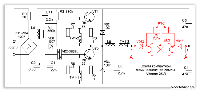
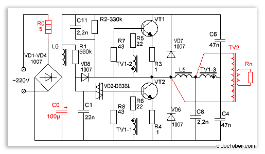
This is one of the most common electrical circuits for energy saving lamps. To convert the CFL circuit into a pulsed power supply, you need to install only one jumper between points A - A 'and add a pulse transformer with a rectifier. Items that can be deleted are marked in red.
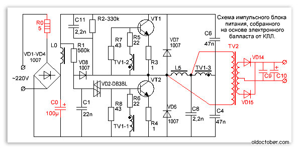
And this is an already completed circuit of a pulsed power supply, assembled on the basis of CFLs using an additional pulse transformer.
For simplicity, the fluorescent lamp and a few parts have been removed and replaced with a jumper.
As you can see, the CFL circuit does not require major changes. Additional elements introduced into the scheme are marked in red.
What power supply unit can be made from CFL?
The power of the power supply is limited by the overall power of the pulse transformer, the maximum permissible current of the key transistors and the size of the cooling radiator, when used.
A low-power power supply can be built by winding the secondary winding directly onto the frame of an existing choke from the lamp unit.

If the choke window does not allow winding the secondary winding or if you need to build a power supply unit with a power that significantly exceeds the power of the CFL, then you will need an additional pulse transformer.
If you want to get a power supply with a power of more than 100 watts, and ballast from a 20-30 watt lamp is used, then most likely you will have to make minor changes to the electronic ballast circuit.
In particular, it may be necessary to install more powerful VD1-VD4 diodes in the input bridge rectifier and rewind the input choke L0 with a thicker wire. If the current gain of the transistors is insufficient, then the base current of the transistors will have to be increased by reducing the values \u200b\u200bof the resistors R5, R6. In addition, you will have to increase the power of the resistors in the base and emitter circuits.
If the generation frequency is not very high, then it may be necessary to increase the capacitance of the blocking capacitors C4, C6.
Pulse transformer for power supply.

A feature of self-excited half-bridge switching power supplies is the ability to adapt to the parameters of the used transformer. And the fact that the feedback loop will not pass through our homemade transformer makes the task of calculating the transformer and setting up the unit even easier. Power supplies assembled according to these schemes forgive errors in calculations up to 150% and higher.
To increase the power of the power supply, a TV2 pulse transformer had to be wound. In addition, I increased the capacitance of the mains voltage filter C0 to 100µF.
Since the efficiency of the power supply is not at all 100%, we had to screw some radiators to the transistors.
After all, if the efficiency of the unit is even 90%, you will still have to dissipate 10 watts of power.

I was not lucky, in my electronic ballast transistors 13003 pos. 1 of such a design were installed, which, apparently, is designed to be attached to the radiator using shaped springs. These transistors do not need spacers, since they are not equipped with a metal pad, but they give off heat much worse. I replaced them with transistors 13007 pos. 2 with holes so that they could be screwed to the radiators with ordinary screws. In addition, 13007 have several times higher maximum permissible currents.
If you wish, you can safely screw both transistors onto one radiator. I checked it works.

Only, the housings of both transistors must be insulated from the heatsink housing, even if the heatsink is inside the electronics housing.
It is convenient to fasten it with M2.5 screws, on which you must first put on insulating washers and pieces of insulating tube (cambric). It is allowed to use KPT-8 heat-conducting paste, as it does not conduct current.

Attention! The transistors are under mains voltage, therefore, the insulating gaskets must ensure electrical safety conditions!

The drawing shows the connection of a transistor with a cooling radiator in section.
- Screw M2.5.
- Washer М2.5.
- Insulating washer M2.5 - fiberglass, textolite, getinax.
- Transistor housing.
- The gasket is a piece of tube (cambric).
- Gasket - mica, ceramics, fluoroplastic, etc.
- Cooling radiator.
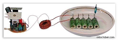
And this is a working 100-watt switching power supply.
The dummy load resistors are immersed in water as their power is insufficient.
The power allocated to the load is 100 watts.
Self-oscillation frequency at maximum load - 90 kHz.
Self-oscillation frequency without load - 28.5 kHz.
The temperature of the transistors is 75ºC.
The area of \u200b\u200bthe radiators of each transistor is 27 cm².
Choke temperature TV1 - 45ºC.
TV2 - 2000NM (Ø28 x Ø16 x 9mm)
Rectifier.
All secondary rectifiers of a half-bridge switching power supply must be full-wave. If this condition is not met, then the magnetic conductor may enter saturation.
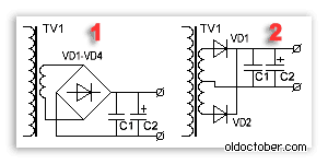
There are two common full-wave rectifier circuits.
1. Bridge scheme.
2. Circuit with zero point.
The bridge circuit saves a meter of wire, but dissipates twice as much energy on the diodes.
The zero point circuit is more economical, but requires two perfectly symmetrical secondary windings. Asymmetry in the number of turns or location can lead to saturation of the magnetic circuit.
However, it is the zero-point circuits that are used when it is required to obtain large currents at a low output voltage. Then, for additional minimization of losses, instead of conventional silicon diodes, Schottky diodes are used, on which the voltage drop is two to three times less.
Example.
Rectifiers of computer power supplies are made according to the zero point scheme. With a power output of 100 watts and a voltage of 5 volts, 8 watts can dissipate even on Schottky diodes.
100/5 * 0.4 \u003d 8 (Watt)
If we use a bridge rectifier, and even ordinary diodes, then the power dissipated on the diodes can reach 32 watts or even more.
100/5 * 0.8 * 2 \u003d 32 (Watt).
Pay attention to this when you design the power supply, so that later you do not look for where half the power disappeared.

In low voltage rectifiers, it is better to use a zero point circuit. Moreover, with manual winding, you can simply wind the winding in two wires. In addition, high-power switching diodes are not cheap.
How to properly connect the switching power supply to the network?

To set up switching power supplies, they usually use the following connection scheme. Here, the incandescent lamp is used as a ballast with a non-linear characteristic and protects the UPS from failure during abnormal situations. The power of the lamp is usually chosen close to the power of the pulsed power supply under test.
When a pulsed power supply unit is operating at idle or at a low load, the resistance of the lamp cocoa filament is small and it does not affect the operation of the unit. When, for some reason, the current of the key transistors increases, the spiral of the lamp becomes heated and its resistance increases, which leads to the limitation of the current to a safe value.
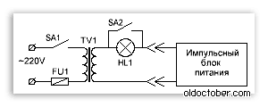
This drawing shows a diagram of a stand for testing and adjusting pulsed power supplies that meets electrical safety standards. The difference between this circuit and the previous one is that it is equipped with an isolation transformer, which provides galvanic isolation of the UPS under study from the lighting network. The SA2 switch allows you to block the lamp when the power supply delivers more power.

And this is already an image of a real stand for repair and adjustment of pulsed power supplies, which I made many years ago according to the diagram above.
An important operation when testing a PSU is a dummy load test. It is convenient to use powerful resistors such as PEV, PPB, PSB, etc. as a load. These "glass ceramic" resistors are easy to find on the radio market for their green color scheme. Red numbers are power dissipation.

It is known from experience that the capacity of the equivalent load for some reason is always not enough. The resistors listed above can dissipate power two to three times the nominal for a limited time. When the power supply unit is turned on for a long time to check the thermal regime, and the power of the equivalent load is insufficient, then the resistors can simply be dipped into the water.
Be careful not to burn!
Terminating resistors of this type can heat up to a temperature of several hundred degrees without any external manifestations!
That is, you will not notice any smoke or color change and you can try to touch the resistor with your fingers.
How to set up a switching power supply?
Actually, the power supply, assembled on the basis of a serviceable electronic ballast, does not require special adjustment.
It must be connected to a dummy load and make sure that the PSU is capable of delivering the rated power.
During a run under maximum load, you need to follow the dynamics of the temperature rise of transistors and transformer. If the transformer heats up too much, then you need to either increase the wire cross-section, or increase the overall power of the magnetic circuit, or both.
If the transistors are very hot, then you need to install them on the radiators.
If a home-wound choke from CFL is used as a pulse transformer, and its temperature exceeds 60 ... 65 ° C, then it is necessary to reduce the load power.
It is not recommended to raise the temperature of the transformer above 60… 65 ° C, and of transistors above 80… 85 ° C.
What is the purpose of the elements of the switching power supply circuit?
R0 - limits the peak current flowing through the rectifier diodes at the moment of switching on. CFLs also often function as a fuse.
VD1… VD4 is a bridge rectifier.
L0, C0 - power filter.
R1, C1, VD2, VD8 - converter start circuit.
The launch node works as follows. The capacitor C1 is charged from the source through the resistor R1. When the voltage across the capacitor C1 reaches the breakdown voltage of the VD2 dinistor, the dinistor unlocks itself and unlocks the VT2 transistor, causing self-oscillations. After the onset of generation, rectangular pulses are applied to the cathode of the VD8 diode and the negative potential reliably blocks the VD2 dinistor.
R2, C11, C8 - make it easier to start the converter.
R7, R8 - improve the blocking of transistors.
R5, R6 - limit the base current of the transistors.
R3, R4 - prevent saturation of transistors and act as fuses during breakdown of transistors.
VD7, VD6 - protect transistors from reverse voltage.
TV1 is a feedback transformer.
L5 - ballast choke.
C4, C6 - blocking capacitors, on which the supply voltage is divided in half.
TV2 is a pulse transformer.
VD14, VD15 - pulse diodes.
C9, C10 - filter capacitors.
Energy-saving lamps are widely used in everyday life and at work, over time they become unusable, and yet many of them can be restored after a simple repair. If the lamp itself is out of order, then a rather powerful power supply unit for any required voltage can be made from the electronic "filling".
What does a power supply from an energy-saving lamp look like?
In everyday life, a compact, but at the same time, a powerful low-voltage power supply is often required; this can be done using a failed energy-saving lamp. In lamps, lamps most often fail, and the power supply remains in working order.
In order to make a power supply, it is necessary to understand the principle of operation of the electronics contained in the energy-saving lamp.
Advantages of switching power supplies
In recent years, there has been a clear tendency to move away from classical transformer power supplies to switching power supplies. This is due, first of all, to the large disadvantages of transformer power supplies, such as large mass, low overload capacity, low efficiency.
The elimination of these shortcomings in switching power supplies, as well as the development of the element base, made it possible to widely use these power nodes for devices with a power from a few watts to many kilowatts.
Power supply circuit
The principle of operation of a switching power supply in an energy-saving lamp is exactly the same as in any other device, for example, a computer or TV.
In general terms, the operation of a switching power supply can be described as follows:
- AC mains current is converted into DC without changing its voltage, i.e. 220 V.
- A transistor pulse width converter converts DC voltage into rectangular pulses, with a frequency of 20 to 40 kHz (depending on the lamp model).
- This voltage is fed through the choke to the luminaire.
Let us consider the scheme and operation of the switching lamp power supply (figure below) in more detail.

Energy-saving lamp electronic ballast circuit
The mains voltage is fed to the bridge rectifier (VD1-VD4) through a limiting resistor R 0 of small resistance, then the rectified voltage is smoothed on a filtering high-voltage capacitor (C 0), and through a smoothing filter (L0) is fed to the transistor converter.
The start of the transistor converter occurs at the moment when the voltage across the capacitor C1 exceeds the opening threshold of the VD2 dinistor. This will start the generator on transistors VT1 and VT2, due to which self-generation occurs at a frequency of about 20 kHz.
Other circuit elements such as R2, C8 and C11 play a supporting role in making it easier to start the generator. Resistors R7 and R8 increase the closing speed of the transistors.
And resistors R5 and R6 serve as limiting resistors in the base circuits of transistors, R3 and R4 protect them from saturation, and in case of breakdown they play the role of fuses.
Diodes VD7, VD6 are protective, although in many transistors designed to work in such devices, such diodes are built-in.
TV1 is a transformer, from its windings TV1-1 and TV1-2, the feedback voltage from the generator output is supplied to the base circuits of the transistors, thereby creating conditions for the generator to operate.
In the figure above, the parts to be removed when reworking the block are highlighted in red, points А – А` must be connected with a jumper.
Block rework
Before proceeding with the alteration of the power supply, you should decide on what current power you need to have at the output, the depth of modernization will depend on this. So, if a power of 20-30 W is required, then the alteration will be minimal and will not require much intervention in the existing circuit. If it is necessary to obtain a power of 50 or more watts, then a more thorough modernization will be required.
It should be borne in mind that the output of the power supply will be DC voltage, not AC. It is impossible to get an alternating voltage of 50 Hz from such a power supply.
Determine the power
Power can be calculated using the formula:
Р - power, W;
I - current strength, A;
U - voltage, V.
For example, take a power supply with the following parameters: voltage - 12 V, current - 2 A, then the power will be:
Taking into account the overload, 24-26 W can be taken, so for the manufacture of such a unit, minimal intervention in the circuit of a 25 W energy-saving lamp is required.
New parts

Adding new parts to the diagram
The added details are highlighted in red, these are:
- diode bridge VD14-VD17;
- two capacitors C 9, C 10;
- additional winding placed on the ballast choke L5, the number of turns is selected empirically.
The added winding to the choke plays another important role of the isolation transformer, preventing mains voltage from entering the power supply output.
To determine the required number of turns in the added winding, you should do the following:
- a temporary winding is wound on the choke, about 10 turns of any wire;
- connected with a load resistance, with a power of at least 30 W and a resistance of about 5-6 ohms;
- include in the network, measure the voltage across the load resistance;
- the resulting value is divided by the number of turns, they find out how many volts are per 1 turn;
- calculate the required number of turns for a constant winding.
A more detailed calculation is given below.

Test inclusion of a converted power supply
After that, it is easy to calculate the required number of turns. To do this, the voltage that is planned to be obtained from this unit is divided by the voltage of one turn, the number of turns is obtained, and about 5-10% is added to the result.
W \u003d U out / U vit, where
W is the number of turns;
U out - the required output voltage of the power supply;
U vit - voltage per one turn.

Winding an additional winding on a standard choke
The original choke winding is under mains voltage! When winding an additional winding over it, it is necessary to provide interwinding insulation, especially if a PEL-type wire is wound, in enamel insulation. For interwinding insulation, polytetrafluoroethylene tape can be used to seal threaded connections, which is used by plumbers, its thickness is only 0.2 mm.
The power in such a unit is limited by the overall power of the used transformer and the permissible current of the transistors.
High power power supply
This will require a more complex upgrade:
- additional transformer on a ferrite ring;
- replacement of transistors;
- installation of transistors on radiators;
- an increase in the capacity of some capacitors.
As a result of this upgrade, a power supply unit with a power of up to 100 W is obtained, with an output voltage of 12 V. It is capable of providing a current of 8-9 amperes. This is enough to power, for example, a medium power screwdriver.
The diagram of the upgraded power supply is shown in the figure below.

100 W power supply
As you can see in the diagram, the resistor R 0 is replaced with a more powerful (3-watt) resistor, its resistance is reduced to 5 ohms. It can be replaced with two 2-watt 10 ohms by connecting them in parallel. Further, C 0 - its capacity is increased to 100 microfarads, with an operating voltage of 350 V. If it is undesirable to increase the dimensions of the power supply, then you can find a miniature capacitor of such a capacity, in particular, it can be taken from a camera-soap dish.
To ensure reliable operation of the unit, it is useful to slightly reduce the values \u200b\u200bof the resistors R 5 and R 6, to 18-15 Ohm, and also to increase the power of the resistors R 7, R 8 and R 3, R 4. If the generation frequency turns out to be low, then the ratings of the capacitors C 3 and C 4 - 68n should be increased.
The most difficult thing can be making a transformer. For this purpose, in pulse units, ferrite rings of appropriate sizes and magnetic permeability are most often used.
Calculation of such transformers is rather complicated, but there are many programs on the Internet with which it is very easy to do, for example, "Lite-CalcIT Pulse Transformer Calculation Program".
![]()
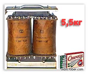
What a pulse transformer looks like
The calculation carried out using this program gave the following results:
A ferrite ring is used for the core, its outer diameter is 40, the inner diameter is 22, and the thickness is 20 mm. The primary winding with a PEL wire - 0.85 mm 2 has 63 turns, and two secondary windings with the same wire - 12.
The secondary winding must be wound in two wires at once, while it is advisable to pre-twist them slightly along the entire length, since these transformers are very sensitive to the asymmetry of the windings. If this condition is not observed, then the VD14 and VD15 diodes will heat up unevenly, and this will further increase the asymmetry, which, in the end, will disable them.
But such transformers easily forgive significant errors when calculating the number of turns, up to 30%.
Since this circuit was originally designed to work with a 20 W lamp, transistors 13003 are installed. In the figure below, position (1) - medium power transistors, they should be replaced with more powerful ones, for example, 13007, as in position (2). They may need to be installed on a metal plate (heat sink) with an area of \u200b\u200babout 30 cm 2.

Test
A test turn-on should be carried out with the observance of certain precautions so as not to damage the power supply:
- Make the first test switch-on through a 100 W incandescent lamp to limit the current to the power supply.
- It is necessary to connect a 3-4 Ohm load resistor to the output, with a power of 50-60 W.
- If everything went well, let it run for 5-10 minutes, turn off and check the degree of heating of the transformer, transistors and rectifier diodes.
If no mistakes were made during the replacement of parts, the power supply should work without problems.
If the test switch-on showed the unit to work, it remains to test it in full load mode. To do this, reduce the resistance of the load resistor to 1.2-2 Ohm and connect it directly to the network without a light bulb for 1-2 minutes. Then turn off and check the temperature of the transistors: if it exceeds 60 0 C, then they will have to be installed on the radiators.
REPAIR AND ALTERATION OF ENERGY SAVING LAMPS
ENERGY SAVING LAMP FROM 12V
I wound it by eye and by memory, interpreting the size of the cores, according to the continuous winding scheme. The first one wound the collector winding of 10 turns with a 0.4mm wire, the second with the base one 6 turns with a 0.2mm wire, laid a layer of insulation and overlapped the load winding with a wire of 0.1, it turned out about 330-340 turns. I connected a lamp from a 7w scanner to the load, the device immediately started working, as evidenced by the light emanating from the lamp. Nearby lay a 13-watt energy-saving lamp with a burnt-out spiral, I decided to try to master this brainchild such a load, I was pleasantly surprised, at a current of half an ampere at a voltage of 12 volts, the lamp shines brightly enough.
It also operates on two lithium-ion batteries, although consuming 150 mA more. I soldered it together with a hinged mounting (4 parts) and all this was miraculously placed in the original case from under the ballast by 220.
The transistor is not very hot, after five minutes of operation you can hold your finger on it. Now this design will go straight to the dacha, where, as usual, there are constant interruptions in electricity, you can drink tea or spread the bed in daylight.
What can you do if your compact fluorescent lamp burns out
Although for economy lamps, depending on the manufacturer, there is a guarantee, and even up to 3 years. But consumers may be faced with the fact that the light bulb burned out, and you did not have the packaging, purchase receipt, the store moved to another place, i.e. for some reason beyond your control, you cannot exchange the broken item. We decided to offer you to take advantage of the original solution for the use of burned out economy lamps that we found in the vastness of the huge Internet resource and offer it to you.
Remember, you are endangering your life when you hit 220V!
The easiest way is to throw it into the trash, but you can make ... another one out of it, and if there are a few burned-out lamps, then you can do .... repair.
If you have held a soldering iron in your hands at least once, then this article is for you.
You can make your own electronic ballast for fluorescent lamps and turn on the lamp up to 30 watts, without a starter and a choke, using a small scarf removed from our economy lamp. In this case, it will light up instantly, when the voltage drops, it will not ‘blink’.
This lamp burns out in two ways:
1) electronic circuit is on

2) the heating coil burns out

First, we find out what happened. We disassemble the lamp (very often assembled on latches, cheaper options are glued).

Turn off the flask, bite off the power wires:


We call the incandescence of the flask (to decide whether to discard the flask or not)

I was not lucky, both heating spirals burned out (for the first time in my considerable practice, usually one, and when the circuit burns out, not a single one). In general, if at least one flask burns out, we throw it away, if not, then it is working, and the circuit burned out.
We debug the working flask for storage (until the next burned out housekeeper) and then we hook the flask to the working diagram. So from several we make 1, and maybe more (as luck would have it).
And here is an option for making a fluorescent lamp. You can connect, as well as a 6 Watt lamp from a "Chinese" lantern (for example, I wrapped it with plastic from a green bottle, and hid the circuit in a burnt out charger, from a mobile phone and got a cool backlight for an aquarium) and a 30 Watt fluorescent lamp:


Can the electronic ballast be repaired?
Fluorescent lamps with electronic ballast can be found everywhere today. Table lamps with rectangular shades and a two-knee holder are very popular. All electrical stores already sell bulbs that are screwed into conventional round-threaded sockets instead of classic incandescent bulbs. In particular, the St. Petersburg metro has recently completely got rid of incandescent lamps, replacing them with fluorescent ones. The advantage of such lamps is obvious - long service life, low power consumption with high luminous efficiency (suffice it to say that an 11-watt fluorescent lamp replaces a 75-watt incandescent lamp), soft light with a spectrum close to natural sunlight.
The leading manufacturers of fluorescent lamps are Philips, Osram and some others. Unfortunately, in the domestic market there are enough low-quality Chinese lamps that come out of standing much more often than their branded counterparts. A detailed story about electronic ballasts, about the principles of operation, advantages, circuitry solutions is in the book "Power Electronics for Professionals and Amateurs". The section of the book is called "Ballast You Can't Drown With. New Methods for Controlling Fluorescent Lighting Lamps." Therefore, readers who need to get the initial
information about electronic ballasts can refer to the book, but here a rather specific issue of repairing lamps that came out of standing is considered.
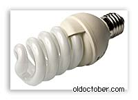
The history of the appearance of this article is associated with the acquisition by the author of a lamp of an unknown company (photo 1). This lamp worked flawlessly in the chandelier for several months, but after this time it simply stopped lighting up. There was nothing left to do but to disassemble the lamp, gently (from the sides) prying the case with a thin screwdriver (it consists of two halves, fastened together by three latching protrusions).


The disassembled lamp is shown in photo 2. It consists of a round base, a control circuit (actually an electronic ballast) and a plastic circle, into which a tube is glued, which gives light. When disassembling the lamp, care should be taken so that, firstly, not to break the balloon and not to damage your hands, eyes and other parts of the body, and secondly, so as not to damage the electronic circuit (do not tear off the "tracks") and the case (plastic) ...

Studies carried out with a multimeter showed that one coil in the bulb of the lamp burned out. Photo 3, which was obtained after opening the balloon, shows that the spiral has burnt out, darkening the phosphor in the vicinity. It was assumed that nothing happened to the electronic ballast (this was later confirmed). With a high degree of confidence, it can be argued that the lamp filament is the weakest point, and in the vast majority of lamps that come out of standing, the filament will burn out rather than the electronic part of the circuit.
By the way, about the electronic circuit of the electronic ballast. It is shown in photo 4. The circuit is redrawn from the printed circuit board. In addition, it does not show some elements that do not affect the fundamentals of ballast operation, and also does not show the ratings. The lamp ballast is a half-bridge push-pull auto-generator with a saturable transformer. Such an autogenerator is well described in books and does not require additional explanations. A diode bridge VD1-VD4 with a C1, C2, L1 filter is installed at the input. Capacitor C1 prevents the penetration of high-frequency noise into the supply network, capacitor C2 serves as a filter for mains ripple, choke L1 limits the inrush current and filters high-frequency interference. The choke L2 and the capacitor C3 are elements of the resonant circuit, the voltage in which "lights" the lamp. Capacitor C4 - starting. It is clear that if one of the threads breaks, the lamp will no longer light up.

A very important element of the circuit is fuse F1. If something happens in the electronic ballast circuit (for example, the half-bridge transistors "burn out", creating a "through" current, or the capacitor C1, C2 breaks through, or the diode bridge breaks through), the fuse will protect the network from a short circuit and possible fire. Photo 5 shows this fuse.

It is a cone without a classic holder with long leads, one of which is soldered to the base, and the other, to the ballast PCB. So if the fuse is blown, most likely something has happened in the ballast circuit, and you need to check its elements. If not, the ballast is probably intact.
The most interesting thing is that such an energy-saving lamp can be repaired, and it will cost less than buying a new lamp. It will, of course, not look as beautiful as an industrial one, but it will look pretty decent (if everything is done carefully). So, you need to purchase a replacement element for a table lamp, for example, such as shown in photo 6. The manufacturer of this lamp is the Italian company Osram, the lamp power is 11 W, which corresponds to 75 W of an incandescent lamp.

The lamp box contains interesting information about the power consumption of other lamps, as well as on reliability. This 9W lamp replaces a 60W incandescent lamp, 9W for 40W and 5W for 25W. The guaranteed MTBF is 10,000 hours, which corresponds to 10 incandescent lamps. This is about 13 months of continuous work. The base of the dump should contain four pins, that is, two spirals (photo 7). For this lamp, the right two leads belong to one spiral, the left two to the other spiral. If the location of the spirals is not obvious, you can always find the desired leads with a multimeter - the spirals have a low resistance of the order of a few ohms.

The lamp leads must be carefully irradiated with solder, avoiding overheating.
Now let's start preparing the base to which we will attach the lamp. A circle, similar to the existing one, filled with white mass (photo 8), you need to make a new one and use a file to prepare a site to which the lamp will be glued (photo 9). It is strongly not recommended to break the lamp bulb.


Then it is better to check how the lamp lights up. We solder the lamp leads to the ballast (photo 11) and connect the ballast to the network. For a break-in, it is worth training it, turning it on and off several times and keeping it on for several hours. The lamp glows with a fairly bright light, and at the same time it heats up, so it is better to put it on a board and cover with a non-combustible sheet. When the training is completed, we disassemble this structure and begin installing the lamp.

We take a tube of Moment superglue and apply a few drops to the mating surfaces. Then we insert the leads into the holes and press the parts tightly to each other, keeping them in this form for half an hour. The glue will securely "grip" the details (photo 10). It is better to use this glue, or dichloroethane, since the plastic must melt a little in the mating place to securely attach.

It remains to assemble the lamp. We solder the ballast into the base, not forgetting about the fuse. In advance (before soldering), you need to solder four wires with which the lamp will be connected to the ballast. Any wire will do, well, it is better that it be an MGTF-type wire in fluoroplastic heat-resistant insulation (photo 12). Assembling the lamp is also simple - just lay the wires inside the base, or twist them with a bundle, and then click the latches. For electrical safety purposes, it is better to seal the holes from the previous cylinder with circles cut from the packaging from dairy products.

The repaired lamp is ready (photo 13). It can be screwed into the chuck.
In conclusion, I note that you can fantasize quite spaciously on the topic of electronic ballasts. For example, insert a lamp into a beautiful lamp and hang it from the ceiling using parts from a burned-out lamp.
Visiting the sites of foreign home-builders, I noticed that the so-called life hacking... Literally, this translates as "life hacking." Do not think anything bad, life hacking has nothing to do with computer hacking! It's just that they call useful tips that help people use seemingly completely unnecessary things - empty cans, PET bottles, burnt out light bulbs, disabled household appliances. They are not thrown away, but simply change their role or go to spare parts for other useful devices. I would like to propose something similar.
Energy saving lamps are gaining popularity. The European Union has already banned the production of conventional incandescent lamps. Unfortunately, energy-saving lamps sometimes fail too. They can, of course, be thrown away and forgotten. Or you can subject her to the hacking procedure. So, we disassemble a burnt out energy-saving lamp. Because, as a rule, only the threads in the bulb itself burn out, and the electronic components in the lamp base are operable with a probability of 99.9%.
To see what color the insides of an energy-saving lamp are, you need to open it. In order not to injure our hands on glass tubes (they are made of thin glass and can burst at any moment), wrap the flask in a plastic bag and grab it with tape. The place of gluing the body is obvious and we are trying to separate its parts with a screwdriver or a powerful knife. If we do it carefully, we will spend 2 minutes.
When the energy-saving lamp falls into three parts, the following picture will open to us:
As you can see, the main parts are a bulb, a board with electronic elements (radio components) and a lamp base. Now let's estimate what and how we can apply.
Energy-saving lamp bulb... Honestly, I haven't figured out what to do with him yet. The flask is a sealed glass envelope coated with a phosphor from the inside. It will hardly be possible to open it painlessly. And using it as some kind of float is unreliable - glass is all the same.
Plinth. This item is already more attractive. He can be given a second life. After all, this is actually a small case, with a contact that can be screwed into any standard E27 or E14 cartridge.

The simplest application is that you can make an extension cord from this base (low-power, of course). Only it will not be possible to plug it into an outlet, but into any cartridge. Perhaps the oldest generation remembers such devices. For some reason they were called "swindler". Such a peculiar adapter "lamp-socket". By the way, it can be very useful in our time. Especially when traveling abroad. Since the system of design of sockets can be original and original in the country and it is not always possible to purchase or select an adapter for it, but you need to charge a mobile phone, laptop, navigator, camera.


