Ippon rs232 pinout. Null modem cable (RS232) wiring
Strictly speaking, an RS-232 cable is the name of a standard that describes the interface for connecting a computer with an RS device - recommended standard, translated as "recommended standard", and 232 is a type number. It was developed back in the 60s of the last century. Today, the new edition of this standard, which was adopted in 1991 by the telecommunications association, is called EIA / TIA-232-E. However, most people continue to use the name "RS-232 cable", which has become firmly attached to the interface.
The above interface provides the connection of the following devices: DTE (Data Terminal Equipment) - DTE (Data Terminal Equipment), and DCE (Data Communications Equipment) - DTE (Data Transfer Equipment). OOD usually means a personal computer, and OOD means a modem. Although the RS-232 cable is also used to connect other peripheral devices (printer, mouse, etc.) to the PEOM, as well as to connect with other computers or controllers. It is important to remember the notation DCE and DTE, as they are used in the names of the interface signals and help to understand the description of the required device implementation.
Originally the RS-232 cable had a 25-pin DB25 connector. The DTE type device was equipped with a female connector. Later they began to use a "stripped-down" version of the interface with 9-pin DB9 connectors. This type of cable is common today.
Wiring the RS-232 cable

The following is the pin assignment of a 9-pin DB9 connector. The list shows the male connector pinouts for data processing equipment such as a personal computer. The socket of the data transmission device is unsoldered in such a way that both connectors are connected via a cable or directly "contact to contact".
1. Carrier Detect - the presence of a carrier frequency.
2. Received Data - received data.
3. Transmitted Data - transmitted data.
4. Data Terminal Ready - DTE readiness.
5. Signal Ground - general.
6. Data Set Read - data set readiness.
7. Request To Send - a request to send.
8. ClearToSend - ready to send.
9. Ring Indicator - the presence of a call signal.
Data is transmitted over the RD and TD circuits. The rest of the circuits are intended for displaying the status of DTR and DSR devices, controlling the transmission of CTS and RTS, as well as indicating the status of RI and CD lines. Only when an external modem is connected to a personal computer, the full set of circuits is used. When connecting others, such as controllers or mice, the selective circuits required by the specific equipment are used. They depend on the hardware and software implementation of the device.
Description and technical parameters

The standard clearly defines the maximum possible RS-232 cable length - 15 meters with a baud rate of 9600 bps. However, in practice, it has been verified that stable operation is achieved even with a longer wire length. It is believed that when using an unshielded cable, the length can be increased to 30 meters, and when using a shielded cable, up to 75 meters. And this is without loss. If you reduce the speed by about half, then the cable length also doubles. It is recommended to use a cable based in this case, each signal wire is paired with a common wire. It is not recommended to combine the cable shield with a common signal cable.
You can often find an RS-232 to USB cable. It is a standard interface, one end of which uses
Problems with the "firmware" of receivers. Lack of COM port. Laptop use
Most "old" computers and laptops purchased more than 5 years ago always had several COM ports (RS-232). At least there has always been at least one RS-232 connector.
Rice. 1. Connector on the computer case
Various external equipment was connected to it: mice, printers, modems, specialized equipment. Therefore, there were no problems with connecting the receiver to the computer for "firmware". It was enough just to connect, run the program to update the receiver's software and calmly do everything necessary.
In modern computers, the RS-232 connector is often absent. This is where problems arise, often very unpleasant. In most receivers, there is no other way of "flashing" other than using "RS-232". And not all receivers have a "USB" input for connecting an external flash drive.
And sometimes there is another problem: the laptop has a "COM" port, but it works with receivers of one model, but not with others. This is due to the violation by the laptop manufacturer of the "RS-232" data transmission standard. They go to this in order to save energy of the battery charge. If the manufacturer of the receiver was technically scrupulous and accurate, then a special microcircuit for the "COM" port will be installed in the receiver. Thanks to this microcircuit, the receiver will work with both a laptop and a computer. But the installation of a microcircuit increases the total cost of the product, and lately, manufacturers are saving even on these trifles! Therefore, there is a problem of incompatibility between laptops and most receivers.
When using a computer, the problem of lack of the necessary "RS-232" ports is solved simply: you need to purchase an additional module with "COM" ports. This board installed in the computer is called "PIC-COM" or simply "COM port board".

Rice. 2. PCI card for a computer with two "COM" ports
If you are not good at computers and have never dealt with the installation of additional equipment in a computer before, then contact a specialist! Otherwise, you can "kill" expensive equipment.
After installing the card in the computer, the operating system "Windows" - "OS" assigns a number to the newly installed ports, for example, "1", "2" ... "25".
When using a laptop, you cannot install a regular board from a computer: the wrong standard and size. There are two ways to solve this problem: expensive, but of high quality, and cheap, but not fully compatible. In the first case, you need to purchase a special board with ports for the laptop. The price of these boards is high, and I could not buy this board, even on order.

Rice. 3. Board for laptop with "COM" port
And here's the catch: "old" and "new" laptops have two different standards for additional equipment! Before purchasing, check the instructions for your laptop!
If you could not purchase a board for a computer or laptop, then there is only one way out: "USB". Almost all modern computer models have a "USB" output, at least two, or even all eight! Various USB to COM converters are available on the market.

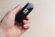
Rice. 4. Converter "USB - COM"

Rice. 5. Scheme of the converter "USB - COM"
How to solder the USB-COM adapter yourself. Option 1
How to make a USB-COM adapter yourself, which can be used to connect converters and other devices to computers that do not have an “iron” COM port.
Attention!
The adapter described below will only match the RX and TX signals.
All other modem signals are inactive.
For most devices without hardware flow control, this is more than enough.
With Pilot VAF / MAF converters, the adapter works 100%
Go!
To assemble you need the following parts:
1. PL2303HX (USB-USART bridge from Prolific) -1pc.
2.MAX232CSE (UART-RS232) -1pc.
3. Quartz 12.00 MHz-1 pc.
4. Capacitors 10 nF (smd1206) -2 pcs.
5. Capacitors 1 uF (smd1206) -6 pcs.
6. Resistors 27 Ohm (smd1206) -2 pcs.
7. Resistors 1.5KΩ (smd1206) -1pc.
8. Connector mini-USB -1 pc.
9. DB-9 male connector - 1 pc.
10. Foil PCB for board 48 * 22mm - 1pc
Adapter circuit
Printed circuit board

Schematic files and seals in the format Eagle PCB Editor can be downloaded from this link
Build and setup
Here, in fact, everything is elementary - we make a board, drill 4 holes and solder all the details.
As a result, you should get such an adapter:

To prevent oxidation, the board can be blown out with polyurethane varnish or any quick-drying car varnish that is at hand.
Next, we connect this device to the USB port of the computer.
Windows will detect a new device and ask for a driver
We go to the site of prolific and download the latest version of firewood
At the time of this writing, the latest driver was this one.
After feeding the driver to Windows, a new Prolific COM port should appear in the system: 
Now you need to check the functionality of the adapter
To do this, on the adapter in the COM port connector, use a screwdriver or wire to close pins 2 and 3 together (on the connector itself, numbers with contact numbers are usually knocked out - take a closer look) Alternatively, you can solder a temporary jumper:
 Next, run the program "Hyperterminal" (Start-> Programs-> Accessories-> Communication-> Hyperterminal)
There is no hyperterminal on whist and seven! Therefore, you will have to go to Google / Yandex to download the hyperterminal or any of its analogs.
We select our new som port in the connection settings:


Now we launch the connection, select the English layout and try to print something.
The symbols of the keys pressed should appear on the screen:

If the letters do not appear, then check the installation
That's all!
Now it remains to remove the jumper from contacts 2-3 and you can use the adapter for its intended purpose.
Those. the input of such a “converter” is connected to a free “USB” connector of the laptop, the driver (control program) is installed from the disk from the kit, and a virtual COM port with the assigned serial number appears in the system settings.
How to solder the USB-COM adapter yourself. Option - 2
| Picture 1.General form |
 |
The proposed block in assembled form allows you to implement the principle: buy - connect. The device will allow users of personal computers to connect devices operating from the COM port (RS232C) to the USB port.
Estimated retail price: 540 rubles
The adapter will be useful in practical applications: for connecting various devices to a personal computer, as well as modems and programmers.
Specifications
Supply voltage from USB port: 5 V.
Consumption current: 20 mA.
RS232C communication speed: 110-230000 bps
Interface: USB1.1, USB2.0.
Supported operating systems: Win98, Win2000, WinXP, Vista, Linux, etc.
Overall dimensions of the device: 60x30 mm.
Contents of delivery
Adapter block assembly: 1.
Instructions: 1.
Design
Structurally, the adapter is made on a double-sided printed circuit board made of foil-clad fiberglass, protected by a transparent heat-shrinkable tube.
The adapter provides all modem signals: DSR, DTR, RTS, CTS, RI, DCD, as well as the main signals RXD and TXD.

Figure 2. Electrical schematic diagram
.gif)
Figure 3. View of the printed circuit board from the side of parts
Block operation description
The schematic diagram is shown on pic 2.
The central part of the device is a CP2102 microcontroller manufactured by SILICON LABORATORIES. A MAX3243 converter manufactured by Texas Instruments is used as a level driver microcircuit. The adapter provides all modem signals: DSR, DTR, RTS, CTS, RI, DCD, as well as the main signals RXD and TXD.
Installing the device in the OSTo install drivers for your computer, you must first download the driver appropriate for your operating system.
Next, install the driver on your personal computer. Connect the adapter. The operating system will detect it and "ask" for the driver, you should tell it the location of this driver (the place where it was unpacked).
After successful installation, the LED on the adapter should light up, signaling the readiness of the device for operation!
NEW Updated driver from 01/25/2011
1. Driver for Win Vista you can download
2. Driver for Windows 2000 / XP / Server 2003 / Vista (v5.0) You can download
3. Driver for Linux you can download
4. Driver for Win98SE you can download
5. Driver for OC Mac you can download
6. an144sw.zip- using this program, you can change the ID codes of the USB-COM adapter. This is necessary in order to be able to use several 8050s on one PC. Use for advanced users only! You can download
PERFORMANCE CHECK BM8050 WITHOUT EXTERNAL EQUIPMENT
To check the transmission and reception of all necessary modem signals according to the connection of the COM device.

Place jumpers on pins 2-3, 4-6, 7-8 of the BM8050 COM-connector.
Connect the device to the USB port of the PC.
See which port the OS has allocated for the device, for which go to Start --- Settings --- Control Panel --- System --- Hardware --- Device Manager --- Ports (COM and LPT) --- Silicon Labs CP210x USB to UART Bridge (COM1).
Launch the standard HiperTerminal application for Windows from Start --- Programs --- Accessories --- Communication --- HiperTerminal.
Stop the running connection, if it is active, for which click the Call --- Stop above.
See which port is used by the program to communicate with the device, for which go to the top left File --- Properties and opposite "Connect via" select the same port as in the Device Manager (in our case, COM1).
In the same window, make sure that the "Hardware" flow control is selected in the program, for which click the button in the center "Configure" and in the lower "Flow control" window select "Hardware".
Exit the program settings by clicking OK, OK again.
Type the text "Text" in the HiperTerminal software, and the text "Text" is printed on the screen, which confirms that the device is working.
Remove the jumpers from contacts 2-3, 4-6, 7-8 of the BM8050 COM connector.

Type the text "Text" in the HiperTerminal software, and there is no print on the screen, which confirms that the device is working.
Driver setup and port selection for USB-COM adapter
Here the first problems await us: firstly, the OS could assign a too large number to the virtual port, for example, "25". And the program for "flashing" the receiver allows you to work with port numbers from one to four. Secondly, not all USB-COM converters can work with the firmware and the receiver itself. The reason is that equipment manufacturers have made their products and programs for them in different ways. It is necessary to check all converters individually for your program and your receiver. It often happens that the converter works with one piece of equipment, but not with the other.
If the first problem is fixed by changing the port number in the OS settings, then the problem of hardware, program and converter compatibility cannot be fixed.
To change the number assigned to the asset, you must change it manually. To do this, you need to enter the "Device Manager": "Start" - "Settings" - "Control Panel" - "System".

Rice. 15.6. "Control Panel"
In the window that appears, select the "Hardware" tab and click on the "Device Manager" button. The Device Manager window opens. In the window that appears, in the tree-like list, select the line “Ports (COM and LPT). In the drop-down list, you will see all the ports available on your computer. Select your virtual port: "USB to COM converter". I have a "Prolific" model converter.

Rice. 15.7. List of available ports
Click on this line with the RIGHT mouse button, in the window that opens, select the "Properties" construction.

Rice. 15.8. Configuring the selected port
In the window that appears, select the "Port Settings" tab. In the line "Speed" select "115200", then click on the "Advanced" button.

Rice. 15.9. Configuring Port Parameters
At the bottom of the window that opens, find the "COM port number" tab.

Rice. 16. Changing the COM port number
Click on the tab and select the desired COM port number.
Note that some of the port numbers may be occupied by existing hardware, such as an internal modem. You cannot use one port at a time!
After completing the configuration, click "OK" to save the changes and completely exit the settings mode by closing all previously open windows. Then restart your computer to make the necessary changes. If you changed the "COM" number of the "USB-COM" port of the converter, then you just need to remove it from the computer connector and reconnect it.
Ready-made solutions for USB-COM adapters from manufacturers.
Adapter cable COM 9 / 25M -> USB AM 1m
Price - RUB 300
Description A cable for connecting devices with a serial interface (RS-232) to the USB port.
Cable or adapter connectors COM25M, COM9M, USB A
Compatibility
USB 1.1 / 2.0 compliant
Supports Windows 2000, Windows XP
Other
Cable length 1 meter
Logistics
Package dimensions (measured in NIKS) 21.5 x 14.5 x 4.1 cm
Gross weight (measured in NIKS) 0.136 kg
TRENDnet Adapter Cable 
Price - RUB 500
The main
Brand TRENDnet
Model TU-S9
Equipment type Adapter cable
Diameter 28/24 AWG
Performance parameters
Data transfer rate 500 Kbps
Powered by USB port
Power Consumption 500mA - Maximum
Compatibility
System Requirements RAM 64 MB
Supports Windows ME, Windows 2000, Windows XP
Other
RoHS Compliance
Cable length 0.6 meters
Weight 75 grams
Working temperature 0 ~ 40 ° C
Package dimensions (measured in NICS) 23 x 16.8 x 4.6 cm
Gross weight (measured in NIKS) 0.135 kg
External sources of information
Link to the manufacturer's website www.trendnet.com
Adapter - USB-COM (RS-232) adapter
Price - RUB 1,500
The adapter is intended for the use of devices and adapters designed to be switched on via the Com (RS232) port, for example, this is very important when using modern computers that have only USB, in this case, using this adapter, you can use modern computers and laptops together with our devices and adapters such as BMW Scanner, Mercedes Scanner, Scanmatik, etc.
Car service equipment, autodiagnostics, diagnostic equipment, auto diagnostics, car scanner, autoscanner, diagnostic post, chip tuning, car diagnostic equipment Carbrain, UNISCAN, ADP-504, KKL-USB, KKL-COM, BMW scanner, Opel scanner, BMW 1.3 .6, Automan, Opel scanner, BMW scanner, motor tester, gas analyzer, engine diagnostics, instrument panel diagnostics Transponder programmer, OBD-2, OBD2, odometer correction, U-581, engine start, crash data, crash date, crash date, speedometer, tachometer.
Although you may need to use a null modem cable (2-3, 3-2, 5-5) and an adapter like -

Add to the adapter USB extension cable here's a straight null modem cable.

- Retail value 100 rub.
- Type A-A
- Length: 1.5m
But for the rest you need " flipped over" null modem cable.

- Retail price RUB 155.00
- Connector type: DB9 F - DB9 F
- Length: 1.8 m
or an adapter like this:
STLab U-350 (RTL) Adapter COM 9M -> USB AM
Price - RUB 350
The main
Manufacturer St-Lab
Model USB DONGLE SERIAL 1 PORT
Description The adapter allows you to connect a device with an RS-232 interface (for example, a modem) to a USB port on your computer.
Equipment type Adapter cable
Connectors for cable or adapter COM9M, USB A
Built-in USB connector Yes
Performance parameters
Baud rate 115200 bps
USB 1.1 interface
Powered by USB port
Supports Windows 2000, Windows ME, Windows XP, Windows Vista, Windows 2003 Server
Package dimensions (measured in NICS) 17 x 13 x 3.2 cm
Gross weight (measured in NIKS) 0.077 kg
External sources of information Link to the manufacturer's website
RS-232 is an interface for data transmission between two devices at a distance of up to 15 meters. The exchange is carried out by wires with digital signals with two voltage levels.
Logic "0" is transmitted with a positive voltage (from +5 to +15 V for the transmitter), and logic "1" is transmitted with a negative voltage (from -5 to -15 V for the transmitter).
RS-232 pinout for DB-9 connector

| Contact | Designation | Direction | Name | Description |
| 1 | CD | entrance | Carrier Detect | Carrier detection |
| 2 | RXD | entrance | Receive Data | Receiving data |
| 3 | TXD | Exit | Transmit Data | Data transfer |
| 4 | DTR | Exit | Data Terminal Ready | Terminal equipment readiness |
| 5 | GND | --- | System Ground | Common wire |
| 6 | DSR | entrance | Data Set Ready | Transmission equipment readiness |
| 7 | RTS | Exit | Request to Send | Transfer request |
| 8 | CTS | entrance | Clear to send | Ready to transmit |
| 9 | RI | entrance | Ring indicator | Call signal |
The type of cable used in our products
Our interface converters use a modem (straight-through) cable. This means that Tx and Rx have been swapped on the inverter side. Handshaking tones are not used, converted or transmitted. From the side of the converter, pins 1,4,6,7,8,9 are not connected.

Distance and baud rate
The cable length depends on the Maximum baud rate. The longer the cable, the greater its capacity, and a lower speed is required for reliable transmission. The maximum distance is usually considered to be 15 m, but this is not standardized. The table below shows an approximate dependence of the cable length on the data exchange rate.

Start bit- mandatory bit, indicating the beginning of the transmitted byte.
Data- 7 or 8 data bits. The least significant bit is transmitted first.
Parity bit is an optional bit. It can be used for the following purposes:
- parity check (EVEN), complements the transmitted character so that the number of ones in the transmitted character is even;
- odd parity check (ODD), complements the transmitted character so that the number of ones in the transmitted character is odd;
- byte marking (MARK) in 9-bit mode is set to one to allocate the device address byte;
- byte marking (SPACE) in 9-bit mode is set to zero to indicate the data byte of the transmitted packet;
If the parity bit is not used, then the corresponding COM port setting is set to "NONE".
Stop bit- a mandatory bit, indicating the completion of the byte transfer.
Zero modem cable is a very useful thing in the satellite industry. Primarily for flashing satellite receivers. But it is not always possible to buy it, so you have to do it yourself.

As I already said 0-modem cable it is useful to us first of all for flashing satellite receivers. And if you can use a short one for this, which is easier to buy, then for cardsharing through a computer you almost always need a long or very long one (made up to 15 m). And it's better to solder this one yourself. Moreover, it is done quite easily.
How to do it yourself null modem cable (RS232) cord for firmware tuner with your own hands?
We will need two DB-9F connectors, a soldering iron, solder, a twisted-pair cable, which suits me just right (you can also have another one at hand, a telephone one normally), circuits and skillful hands.
There are several connection options, but most often you need a three-pin cable. Well, if this does not work, then we make a full one for all contacts in accordance with the pictures below.

An incomplete zero modem cable is almost always suitable. But he also has varieties when his contacts go
Contacts 2 - 2 and 3 - 3, 5-5 direct
Pins 2 - 3 and 3 - 2, 5 - 5 not direct
It is the latter that is not straightforward most often suitable.
The wiring of the rs-232 com port in satellite receivers can look like “daddy” and “mommy”.
“Nurses” are much more common, so I advise you to do with two “mothers” at the ends.
Precisely indirect null modem cable with two mothers, and with right-to-left calculation, suitable for flashing most satellite receivers, or for sharing.
Problems with the "firmware" of receivers. Lack of COM port. Laptop use
Most "old" computers and laptops purchased more than 5 years ago always had several COM ports (RS-232). At least there has always been at least one RS-232 connector.
Rice. 1. Connector on the computer case
Various external equipment was connected to it: mice, printers, modems, specialized equipment. Therefore, there were no problems with connecting the receiver to the computer for "firmware". It was enough just to connect, run the program to update the receiver's software and calmly do everything necessary.
In modern computers, the RS-232 connector is often absent. This is where problems arise, often very unpleasant. In most receivers, there is no other way of "flashing" other than using "RS-232". And not all receivers have a "USB" input for connecting an external flash drive.
And sometimes there is another problem: the laptop has a "COM" port, but it works with receivers of one model, but not with others. This is due to the violation by the laptop manufacturer of the "RS-232" data transmission standard. They go to this in order to save energy of the battery charge. If the manufacturer of the receiver was technically scrupulous and accurate, then a special microcircuit for the "COM" port will be installed in the receiver. Thanks to this microcircuit, the receiver will work with both a laptop and a computer. But the installation of a microcircuit increases the total cost of the product, and lately, manufacturers are saving even on these trifles! Therefore, there is a problem of incompatibility between laptops and most receivers.
When using a computer, the problem of lack of the necessary "RS-232" ports is solved simply: you need to purchase an additional module with "COM" ports. This board installed in the computer is called "PIC-COM" or simply "COM port board".
Rice. 2. PCI card for a computer with two "COM" ports
If you are not good at computers and have never dealt with the installation of additional equipment in a computer before, then contact a specialist! Otherwise, you can "kill" expensive equipment.
After installing the card in the computer, the operating system "Windows" - "OS" assigns a number to the newly installed ports, for example, "1", "2" ... "25".
When using a laptop, you cannot install a regular board from a computer: the wrong standard and size. There are two ways to solve this problem: expensive, but of high quality, and cheap, but not fully compatible. In the first case, you need to purchase a special board with ports for the laptop. The price of these boards is high, and I could not buy this board, even on order.
Rice. 3. Board for laptop with "COM" port
And here's the catch: "old" and "new" laptops have two different standards for additional equipment! Before purchasing, check the instructions for your laptop!
If you could not purchase a board for a computer or laptop, then there is only one way out: "USB". Almost all modern computer models have a "USB" output, at least two, or even all eight! Various USB to COM converters are available on the market.
Rice. 4. Converter "USB - COM"
Rice. 5. Scheme of the converter "USB - COM"
How to solder the USB-COM adapter yourself. Option 1
How to make a USB-COM adapter yourself, which can be used to connect converters and other devices to computers that do not have an “iron” COM port.
Attention!
The adapter described below will only match the RX and TX signals.
All other modem signals are inactive.
For most devices without hardware flow control, this is more than enough.
With Pilot VAF / MAF converters, the adapter works 100%
Go!
To assemble you need the following parts:
1. PL2303HX (USB-USART bridge from Prolific) -1pc.
2.MAX232CSE (UART-RS232) -1pc.
3. Quartz 12.00 MHz-1 pc.
4. Capacitors 10 nF (smd1206) -2 pcs.
5. Capacitors 1 uF (smd1206) -6 pcs.
6. Resistors 27 Ohm (smd1206) -2 pcs.
7. Resistors 1.5KΩ (smd1206) -1pc.
8. Connector mini-USB -1 pc.
9. DB-9 male connector - 1 pc.
10. Foil PCB for board 48 * 22mm - 1pc
Adapter circuit
Printed circuit board
Schematic files and seals in the format Eagle PCB Editor can be downloaded from this link
Build and setup
Here, in fact, everything is elementary - we make a board, drill 4 holes and solder all the details.
As a result, you should get such an adapter:
To prevent oxidation, the board can be blown out with polyurethane varnish or any quick-drying car varnish that is at hand.
Next, we connect this device to the USB port of the computer.
Windows will detect a new device and ask for a driver
We go to the site of prolific and download the latest version of firewood
At the time of this writing, the latest driver was this one.
After feeding the driver to Windows, a new Prolific COM port should appear in the system:
Now you need to check the functionality of the adapter
To do this, on the adapter in the COM port connector, use a screwdriver or wire to close pins 2 and 3 together (on the connector itself, numbers with contact numbers are usually knocked out - take a closer look) Alternatively, you can solder a temporary jumper:
Next, run the program "Hyperterminal" (Start-> Programs-> Accessories-> Communication-> Hyperterminal)
There is no hyperterminal on whist and seven! Therefore, you will have to go to Google / Yandex to download the hyperterminal or any of its analogs.
We select our new som port in the connection settings:
Now we launch the connection, select the English layout and try to print something.
The symbols of the keys pressed should appear on the screen:
If the letters do not appear, then check the installation
That's all!
Now it remains to remove the jumper from contacts 2-3 and you can use the adapter for its intended purpose.
Those. the input of such a “converter” is connected to a free “USB” connector of the laptop, the driver (control program) is installed from the disk from the kit, and a virtual COM port with the assigned serial number appears in the system settings.
How to solder the USB-COM adapter yourself. Option - 2
| Picture 1.General form |
|
The proposed block in assembled form allows you to implement the principle: buy - connect. The device will allow users of personal computers to connect devices operating from the COM port (RS232C) to the USB port.
Estimated retail price: 540 rubles
The adapter will be useful in practical applications: for connecting various devices to a personal computer, as well as modems and programmers.
Specifications
Supply voltage from USB port: 5 V.
Consumption current: 20 mA.
RS232C communication speed: 110-230000 bps
Interface: USB1.1, USB2.0.
Supported operating systems: Win98, Win2000, WinXP, Vista, Linux, etc.
Overall dimensions of the device: 60x30 mm.
Contents of delivery
Adapter block assembly: 1.
Instructions: 1.
Design
Structurally, the adapter is made on a double-sided printed circuit board made of foil-clad fiberglass, protected by a transparent heat-shrinkable tube.
The adapter provides all modem signals: DSR, DTR, RTS, CTS, RI, DCD, as well as the main signals RXD and TXD.
Figure 2. Electrical schematic diagram
Figure 3. View of the printed circuit board from the side of parts
Block operation description
The schematic diagram is shown on pic 2.
The central part of the device is a CP2102 microcontroller manufactured by SILICON LABORATORIES. A MAX3243 converter manufactured by Texas Instruments is used as a level driver microcircuit. The adapter provides all modem signals: DSR, DTR, RTS, CTS, RI, DCD, as well as the main signals RXD and TXD.
Installing the device in the OSTo install drivers for your computer, you must first download the driver appropriate for your operating system.
Next, install the driver on your personal computer. Connect the adapter. The operating system will detect it and "ask" for the driver, you should tell it the location of this driver (the place where it was unpacked).
After successful installation, the LED on the adapter should light up, signaling the readiness of the device for operation!
NEW Updated driver from 01/25/2011
1. Driver for Win Vista you can download
2. Driver for Windows 2000 / XP / Server 2003 / Vista (v5.0) You can download
3. Driver for Linux you can download
4. Driver for Win98SE you can download
5. Driver for OC Mac you can download
6. an144sw.zip- using this program, you can change the ID codes of the USB-COM adapter. This is necessary in order to be able to use several 8050s on one PC. Use for advanced users only! You can download
PERFORMANCE CHECK BM8050 WITHOUT EXTERNAL EQUIPMENT
To check the transmission and reception of all necessary modem signals according to the connection of the COM device.
Place jumpers on pins 2-3, 4-6, 7-8 of the BM8050 COM-connector.
Connect the device to the USB port of the PC.
See which port the OS has allocated for the device, for which go to Start --- Settings --- Control Panel --- System --- Hardware --- Device Manager --- Ports (COM and LPT) --- Silicon Labs CP210x USB to UART Bridge (COM1).
Launch the standard HiperTerminal application for Windows from Start --- Programs --- Accessories --- Communication --- HiperTerminal.
Stop the running connection, if it is active, for which click the Call --- Stop above.
See which port is used by the program to communicate with the device, for which go to the top left File --- Properties and opposite "Connect via" select the same port as in the Device Manager (in our case, COM1).
In the same window, make sure that the "Hardware" flow control is selected in the program, for which click the button in the center "Configure" and in the lower "Flow control" window select "Hardware".
Exit the program settings by clicking OK, OK again.
Type the text "Text" in the HiperTerminal software, and the text "Text" is printed on the screen, which confirms that the device is working.
Remove the jumpers from contacts 2-3, 4-6, 7-8 of the BM8050 COM connector.
Type the text "Text" in the HiperTerminal software, and there is no print on the screen, which confirms that the device is working.
Driver setup and port selection for USB-COM adapter
Here the first problems await us: firstly, the OS could assign a too large number to the virtual port, for example, "25". And the program for "flashing" the receiver allows you to work with port numbers from one to four. Secondly, not all USB-COM converters can work with the firmware and the receiver itself. The reason is that equipment manufacturers have made their products and programs for them in different ways. It is necessary to check all converters individually for your program and your receiver. It often happens that the converter works with one piece of equipment, but not with the other.
If the first problem is fixed by changing the port number in the OS settings, then the problem of hardware, program and converter compatibility cannot be fixed.
To change the number assigned to the asset, you must change it manually. To do this, you need to enter the "Device Manager": "Start" - "Settings" - "Control Panel" - "System".
Rice. 15.6. "Control Panel"
In the window that appears, select the "Hardware" tab and click on the "Device Manager" button. The Device Manager window opens. In the window that appears, in the tree-like list, select the line “Ports (COM and LPT). In the drop-down list, you will see all the ports available on your computer. Select your virtual port: "USB to COM converter". I have a "Prolific" model converter.
Rice. 15.7. List of available ports
Click on this line with the RIGHT mouse button, in the window that opens, select the "Properties" construction.
Rice. 15.8. Configuring the selected port
In the window that appears, select the "Port Settings" tab. In the line "Speed" select "115200", then click on the "Advanced" button.
Rice. 15.9. Configuring Port Parameters
At the bottom of the window that opens, find the "COM port number" tab.
Rice. 16. Changing the COM port number
Click on the tab and select the desired COM port number.
Note that some of the port numbers may be occupied by existing hardware, such as an internal modem. You cannot use one port at a time!
After completing the configuration, click "OK" to save the changes and completely exit the settings mode by closing all previously open windows. Then restart your computer to make the necessary changes. If you changed the "COM" number of the "USB-COM" port of the converter, then you just need to remove it from the computer connector and reconnect it.
Ready-made solutions for USB-COM adapters from manufacturers.
Adapter cable COM 9 / 25M -> USB AM 1m
Price - RUB 300
Description A cable for connecting devices with a serial interface (RS-232) to the USB port.
Cable or adapter connectors COM25M, COM9M, USB A
Compatibility
USB 1.1 / 2.0 compliant
Supports Windows 2000, Windows XP
Other
Cable length 1 meter
Logistics
Package dimensions (measured in NIKS) 21.5 x 14.5 x 4.1 cm
Gross weight (measured in NIKS) 0.136 kg
TRENDnet Adapter Cable
Price - RUB 500
The main
Brand TRENDnet
Model TU-S9
Equipment type Adapter cable
Diameter 28/24 AWG
Performance parameters
Data transfer rate 500 Kbps
Powered by USB port
Power Consumption 500mA - Maximum
Compatibility
System Requirements RAM 64 MB
Supports Windows ME, Windows 2000, Windows XP
Other
RoHS Compliance
Cable length 0.6 meters
Weight 75 grams
Working temperature 0 ~ 40 ° C
Package dimensions (measured in NICS) 23 x 16.8 x 4.6 cm
Gross weight (measured in NIKS) 0.135 kg
External sources of information
Link to the manufacturer's website www.trendnet.com
Adapter - USB-COM (RS-232) adapter
Price - RUB 1,500
The adapter is intended for the use of devices and adapters designed to be switched on via the Com (RS232) port, for example, this is very important when using modern computers that have only USB, in this case, using this adapter, you can use modern computers and laptops together with our devices and adapters such as BMW Scanner, Mercedes Scanner, Scanmatik, etc.
Car service equipment, autodiagnostics, diagnostic equipment, auto diagnostics, car scanner, autoscanner, diagnostic post, chip tuning, car diagnostic equipment Carbrain, UNISCAN, ADP-504, KKL-USB, KKL-COM, BMW scanner, Opel scanner, BMW 1.3 .6, Automan, Opel scanner, BMW scanner, motor tester, gas analyzer, engine diagnostics, instrument panel diagnostics Transponder programmer, OBD-2, OBD2, odometer correction, U-581, engine start, crash data, crash date, crash date, speedometer, tachometer.
Although you may need to use a null modem cable (2-3, 3-2, 5-5) and an adapter like -
Add to the adapter USB extension cable here's a straight null modem cable.
- Retail value 100 rub.
- Type A-A
- Length: 1.5m
But for the rest you need " flipped over" null modem cable.
- Retail price RUB 155.00
- Connector type: DB9 F - DB9 F
- Length: 1.8 m
or an adapter like this:
STLab U-350 (RTL) Adapter COM 9M -> USB AM
Price - RUB 350
The main
Manufacturer St-Lab
Model USB DONGLE SERIAL 1 PORT
Description The adapter allows you to connect a device with an RS-232 interface (for example, a modem) to a USB port on your computer.
Equipment type Adapter cable
Connectors for cable or adapter COM9M, USB A
Built-in USB connector Yes
Performance parameters
Baud rate 115200 bps
USB 1.1 interface
Powered by USB port
Supports Windows 2000, Windows ME, Windows XP, Windows Vista, Windows 2003 Server
Package dimensions (measured in NICS) 17 x 13 x 3.2 cm
Gross weight (measured in NIKS) 0.077 kg
External sources of information Link to the manufacturer's website